


拓扑图如下:
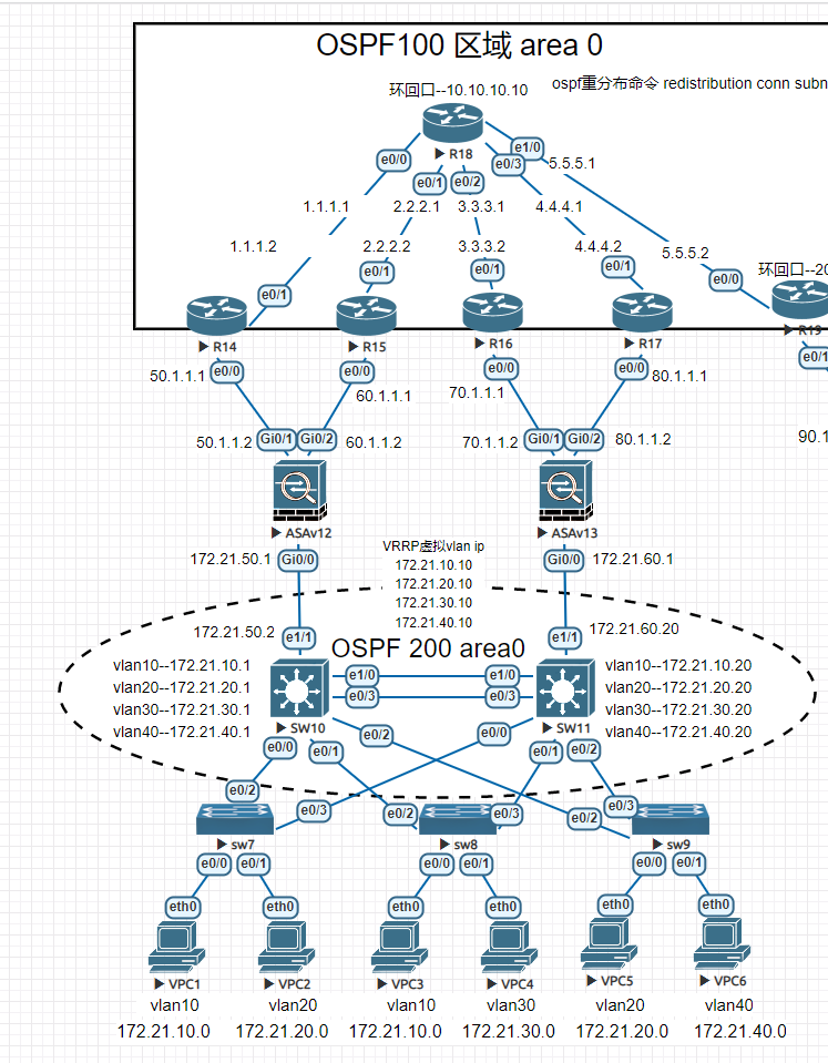
一、组网设计:
该网络采用典型的三层结构:接入层,汇聚层,核心层。为了实现企业高速互联,核心由两个核心节点组成,核心之间采用链路聚合的方式以获得更高的传输效率跟冗余性。核心与防火墙之间采用SLA端口检测功能的方式实现利用ping包检测ISP端口是否通讯使用静态浮动路由实现出口自动切换出口路由的结构保证了网络的可靠性跟网络稳定性。
二、组网中需要用到的网络技术:
1、VLAN:虚拟局域网:用于一个物理LAN划分成多个不同逻辑广播域
2、链路聚合:用于将多个端口绑定在一起,提高带宽,提高可靠性
3、OSPF:开放式最短路径优先:基于链路状态,用于给路由器之间交换自身的路由表
4、路由引入:用于在不同的路由协议之间交换路由
5、NAT:网络地址转换,用于实现私有地址转换成公网地址,以供内部网络访问互联网
6、SLA:端口检测功能,让核心交换机自动切换出口
7、RSTP:快速生成树协议:用于消除环路+链路备份
三、配置过程 注:一下只展示重要配置信息
1.vpc的配置 6台均一样
VPCS> ip dhcp -x 释放ip地址
VPCS> ip dhcp -r DHCP获取IP地址
DDORA IP 172.21.10.2/24 GW 172.21.10.1
VPCS> show ip 检查IP地址
NAME : VPCS[1]
IP/MASK : 172.21.10.2/24
GATEWAY : 172.21.10.1
DNS :
DHCP SERVER : 172.21.10.20
DHCP LEASE : 86334, 86400/43200/75600
MAC : 00:50:79:66:68:01
LPORT : 20000
RHOST:PORT : 127.0.0.1:30000
MTU : 1500
2.接入层交换机配置 三台均一样
!
spanning-tree mode pvst 开启生成树
spanning-tree extend system-id
!
interface Ethernet0/0 pc接入端口配置accsee模式,并将端口划入vlan10中
switchport access vlan 10
switchport mode access
!
interface Ethernet0/1
switchport access vlan 20
switchport mode access
!
interface Ethernet0/2 与核心交换机连接端口采用802.1q封装 trunk模式允许所有vlan通过
switchport trunk encapsulation dot1q
switchport mode trunk
!
interface Ethernet0/3
switchport trunk encapsulation dot1q
switchport mode trunk
3.核心交换机SW10的配置
!
spanning-tree mode rapid-pvst 开启生成树
spanning-tree extend system-id
spanning-tree backbonefast
spanning-tree vlan 10,20,30,40,50,60 priority 4096 给所有vlan开启生成树配置优先级高于sw13上的vlan
!
!
track 10 ip sla 1 reachability 进程track10关联sla 1
!
!
!
interface Port-channel10 端口聚合
switchport trunk encapsulation dot1q 封装802.1q模式trunk允许所有vlan通过
switchport mode trunk
!
interface Ethernet0/0
switchport trunk encapsulation dot1q
switchport mode trunk
!
interface Ethernet0/1
switchport trunk encapsulation dot1q
switchport mode trunk
!
interface Ethernet0/2
switchport trunk encapsulation dot1q
switchport mode trunk
!
interface Ethernet0/3 端口聚合组10挂接到物理端口 模式主动协商
channel-group 10 mode active
!
interface Ethernet1/0
channel-group 10 mode active
!
interface Ethernet1/1 上联防火墙端口配置ip
no switchport
ip address 172.21.50.2 255.255.255.0
!
interface Ethernet1/2
!
interface Ethernet1/3
!
interface Vlan10 给vlan配置ip地址
ip address 172.21.10.1 255.255.255.0
ip helper-address 172.21.10.20 dhcp中继指定dhcp server的IP地址在sw11上
!
interface Vlan10 给vlan配置ip地址
ip address 172.21.10.1 255.255.255.0
ip helper-address 172.21.10.20 dhcp中继指定dhcp server的IP地址在sw11上
standby 1 ip 172.21.10.10 VRRP配置虚拟网关ip
standby 1 timers 30 38
standby 1 priority 245 VRRP 优先级245 (越高越优先)
standby 1 preempt 开启VRRP抢占功能
standby 1 track 10 decrement 10 检测到进程10断开,此vlan优先级减少10
!
interface Vlan20
ip address 172.21.20.1 255.255.255.0
ip helper-address 172.21.20.20
standby 2 ip 172.21.20.10
standby 2 timers 30 38
standby 2 priority 245
standby 2 preempt
standby 2 track 10 decrement 10
!
interface Vlan30
ip address 172.21.30.1 255.255.255.0
ip helper-address 172.21.30.20
standby 3 ip 172.21.30.10
standby 3 timers 30 38
standby 3 priority 245
standby 3 preempt
standby 3 track 10 decrement 10
!
interface Vlan40
ip address 172.21.40.1 255.255.255.0
ip helper-address 172.21.40.20
standby 4 ip 172.21.40.10
standby 4 timers 30 38
standby 4 priority 245
standby 4 preempt
standby 4 track 10 decrement 10
!
router ospf 200 启用ospf协议,宣告sw10自己的网段
router-id 10.10.10.10
redistribute connected subnets
network 172.21.10.0 0.0.0.255 area 0
network 172.21.20.0 0.0.0.255 area 0
network 172.21.30.0 0.0.0.255 area 0
network 172.21.40.0 0.0.0.255 area 0
network 172.21.50.0 0.0.0.255 area 0
default-information originate metric-type 1
!
ip forward-protocol nd
!
ip http server
ip http secure-server
!
ip route 0.0.0.0 0.0.0.0 172.21.50.1 track 10 去往ASA12的默认路由关联track10 (track10在上面已经关联了sla进程1)
ip route 0.0.0.0 0.0.0.0 172.21.60.1 10 去往ASA13的默认路由 优先级为10 默认 为1 越大越优先
!
!
ip sla 1 启用sla,进程为1
icmp-echo 50.1.1.1 source-ip 172.21.50.2 使用端口e1/1的IP地址去ping 运营商ISP的ip是否 正常 (如果运营商禁pin可改ping防火墙的inside口)
frequency 5 每5秒ping一次
ip sla schedule 1 life forever start-time now 从现在开始sla 1开始永远生效
!
!
4.核心交换机SW11的配置
注意:同sw10,多了DHCP的配置(dhcp默认网关一定要指向VRRP虚拟的vlan IP )
!
!
!
ip dhcp pool vlan10
network 172.21.10.0 255.255.255.0
default-router 172.21.10.10 默认网关指向VRRP虚拟的ip,不然sw10关机了,pc无法与网关通讯
!
ip dhcp pool vlan20
network 172.21.20.0 255.255.255.0
default-router 172.21.20.10 默认网关指向VRRP虚拟的ip,不然sw10关机了,pc无法与网关通讯
!
ip dhcp pool vlan30
network 172.21.30.0 255.255.255.0
default-router 172.21.30.10 默认网关指向VRRP虚拟的ip,不然sw10关机了,pc无法与网关通讯
!
ip dhcp pool vlan40
network 172.21.40.0 255.255.255.0
default-router 172.21.40.10 默认网关指向VRRP虚拟的ip,不然sw10关机了,pc无法与网关通讯
!
!
ip cef
no ipv6 cef
!
!
!
spanning-tree mode rapid-pvst
spanning-tree extend system-id
spanning-tree vlan 10,20,30,40,50,60 priority 0
!
!
track 10 ip sla 1 reachability
!
!
!
!
!
!
!
!
!
!
!
!
!
!
interface Port-channel10
switchport trunk encapsulation dot1q
switchport mode trunk
!
interface Ethernet0/0
switchport trunk encapsulation dot1q
switchport mode trunk
!
interface Ethernet0/1
switchport trunk encapsulation dot1q
switchport mode trunk
!
interface Ethernet0/2
switchport trunk encapsulation dot1q
switchport mode trunk
!
interface Ethernet0/3
channel-group 10 mode active
!
interface Ethernet1/0
channel-group 10 mode active
!
interface Ethernet1/1
no switchport
ip address 172.21.60.20 255.255.255.0
!
interface Ethernet1/2
!
interface Ethernet1/3
!
interface Vlan10
ip address 172.21.10.20 255.255.255.0
standby 0 preempt
standby 1 ip 172.21.10.10
standby 1 timers 30 38
standby 1 priority 240 注:sw11作为备用交换机,优先级要低于sw10的245优先级
standby 1 preempt 也可以通过更改优先级实现不同vlan不同出口。
standby 1 track 10 decrement 10
!
interface Vlan20
ip address 172.21.20.20 255.255.255.0
standby 2 ip 172.21.20.10
standby 2 timers 30 38
standby 2 priority 240 注:sw11作为备用交换机,优先级要低于sw10的245优先级
standby 2 preempt 也可以通过更改优先级实现不同vlan不同出口。
standby 2 track 10 decrement 10
!
interface Vlan30
ip address 172.21.30.20 255.255.255.0
standby 3 ip 172.21.30.10
standby 3 timers 30 38
standby 3 priority 240 注:sw11作为备用交换机,优先级要低于sw10的245优先级
standby 3 preempt 也可以通过更改优先级实现不同vlan不同出口。
standby 3 track 10 decrement 10
!
interface Vlan40
ip address 172.21.40.20 255.255.255.0
standby 4 ip 172.21.40.10
standby 4 timers 30 38
standby 4 priority 240 注:sw11作为备用交换机,优先级要低于sw10的245优先级
standby 4 preempt 也可以通过更改优先级实现不同vlan不同出口。
standby 4 track 10 decrement 10
!
router ospf 200 启用ospf协议,宣告sw11自己的网段
router-id 11.11.11.11
redistribute connected subnets
network 172.21.10.0 0.0.0.255 area 0
network 172.21.20.0 0.0.0.255 area 0
network 172.21.30.0 0.0.0.255 area 0
network 172.21.40.0 0.0.0.255 area 0
network 172.21.60.0 0.0.0.255 area 0
default-information originate metric-type 1
!
ip forward-protocol nd
!
ip http server
ip http secure-server
!
ip route 0.0.0.0 0.0.0.0 172.21.60.1 track 1
ip route 0.0.0.0 0.0.0.0 172.21.50.1 10
ip ssh server algorithm encryption aes128-ctr aes192-ctr aes256-ctr
ip ssh client algorithm encryption aes128-ctr aes192-ctr aes256-ctr
!
!
ip sla 1
icmp-echo 172.21.60.1 source-ip 172.21.60.20
frequency 5
ip sla schedule 1 life forever start-time now
!
5.ASAv12的配置 无用信息已删除
!
interface GigabitEthernet0/0
nameif inside
security-level 100
ip address 172.21.50.1 255.255.255.0
!
interface GigabitEthernet0/1
nameif outside
security-level 0
ip address 50.1.1.2 255.255.255.0
!
interface GigabitEthernet0/2
nameif outside2
security-level 0
ip address 60.1.1.2 255.255.255.0
!
!
access-list 100 extended permit ip any any 思科默认禁止所有,建立ACL进程100 允许所有 ip执行所有动作
nat (inside,outside) source dynamic any interface 地址转换
nat (inside,outside2) source dynamic any interface
access-group 100 in interface outside ACL挂接到outside出口上
access-group 100 in interface outside2
route outside 0.0.0.0 0.0.0.0 50.1.1.1 1 track 1 去往运营商的默认路由,关联track进程1
route outside2 0.0.0.0 0.0.0.0 60.1.1.1 10 track 2 去往运营商的默认路由,关联track进程2
route inside 172.21.0.0 255.255.0.0 172.21.50.2 1 去往内网的路由
sla monitor 1 sla检测进程1
type echo protocol ipIcmpEcho 50.1.1.1 interface outside 使用outside检测对端ip
frequency 5
sla monitor schedule 1 life forever start-time now
sla monitor 2
type echo protocol ipIcmpEcho 60.1.1.1 interface outside2 使用outside2检测对端ip
frequency 5
sla monitor schedule 2 life forever start-time now
track 1 rtr 1 reachability track进程1关联sla进程1
!
track 2 rtr 2 reachability track进程2关联sla进程2
6.ASAv13的配置
!
interface GigabitEthernet0/0
nameif inside
security-level 100
ip address 172.21.60.1 255.255.255.0
!
interface GigabitEthernet0/1
nameif outside
security-level 0
ip address 70.1.1.2 255.255.255.0
!
interface GigabitEthernet0/2
nameif outside2
security-level 0
ip address 80.1.1.2 255.255.255.0
!
nat (inside,outside) source dynamic any interface
nat (inside,outside2) source dynamic any interface
access-group 100 in interface outside
access-group 100 in interface outside2
route outside 0.0.0.0 0.0.0.0 70.1.1.1 1 track 1
route outside2 0.0.0.0 0.0.0.0 80.1.1.1 10 track 2
route inside 172.21.0.0 255.255.0.0 172.21.60.20 1
sla monitor 1
type echo protocol ipIcmpEcho 70.1.1.1 interface outside
frequency 5
sla monitor schedule 1 life forever start-time now
sla monitor 2
type echo protocol ipIcmpEcho 80.1.1.1 interface outside2
frequency 5
sla monitor schedule 2 life forever start-time now
!
track 1 rtr 1 reachability
!
track 2 rtr 2 reachability
以上已完成了企业内部的所有配置,下面是模拟运营商使用ospf协议。BGP我不会,所以..........................
R14的配置
interface Ethernet0/0
ip address 50.1.1.1 255.255.255.0
duplex auto
!
interface Ethernet0/1
ip address 1.1.1.2 255.255.255.0
duplex auto
!
!
router ospf 100
router-id 14.14.14.14
network 1.1.1.0 0.0.0.255 area 0 OSPF宣告自己的网段,不包含内部防火墙的网段。
ip route 0.0.0.0 0.0.0.0 1.1.1.1
8.R15的配置信息
!
interface Ethernet0/0
ip address 70.1.1.1 255.255.255.0
duplex auto
!
interface Ethernet0/1
ip address 80.1.1.2 255.255.255.0
duplex auto
!
router ospf 100 OSPF宣告自己所有网段
router-id 15.15.15.15
network 70.1.1.0 0.0.0.255 area 0
network 80.1.1.0 0.0.0.255 area 0
R14-R15-R16-R17配置基本相同,不一一介绍,按拓扑图ip更改即可
9.R18的配置 1个环回口
!
!
interface Loopback0
ip address 10.10.10.10 255.255.255.255
!
interface Ethernet0/0
ip address 1.1.1.1 255.255.255.0
duplex auto
!
interface Ethernet0/1
ip address 2.2.2.1 255.255.255.0
duplex auto
!
interface Ethernet0/2
ip address 3.3.3.1 255.255.255.0
duplex auto
!
interface Ethernet0/3
ip address 4.4.4.1 255.255.255.0
duplex auto
!
interface Ethernet1/0
ip address 5.5.5.1 255.255.255.0
duplex auto
!
router ospf 100
router-id 18.18.18.18
redistribute connected subnets OSPF路由重分布?不太明白
network 1.1.1.0 0.0.0.255 area 0
network 2.2.2.0 0.0.0.255 area 0
network 3.3.3.0 0.0.0.255 area 0
network 4.4.4.0 0.0.0.255 area 0
network 5.5.5.0 0.0.0.255 area 0
network 10.10.10.0 0.0.0.255 area 0
!
ip route 50.1.1.0 255.255.255.0 1.1.1.2 由于asa没有跑ospf,所以我们需要指定去往这些网段的路径
ip route 60.1.1.0 255.255.255.0 2.2.2.2
ip route 70.1.1.0 255.255.255.0 3.3.3.2
ip route 80.1.1.0 255.255.255.0 4.4.4.2
ip route 90.1.1.0 255.255.255.0 5.5.5.2
到此实验完成啦,下面是测试阶段
四、测试阶段
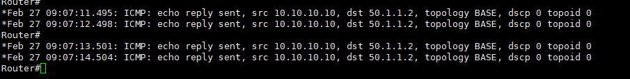
使用VPC1去ping R18的环回口10.10.10.10 下面是R18收到来自ASA12的信息,源IP50.1.1.2
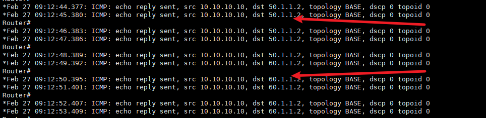
2.将运营商R14关机,由于防火墙ASA12有sla检测,出口自动切换到R15上,源ip60.1.1.2
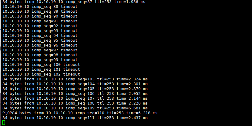
3.将核心交换机sw10直接关机。可以看到pc丢包大概15秒后恢复,源IP变成ASA13上的70.1.1.1
总结:
(1)若需要在三层交换机上配置DHCP服务器,注意只能在其中一台上配置,不能两个都配置。若需要提高自动获取IP功能,那么可以配一台单独服务器,用做DHCP服务器。
(2)上述实验中,vlan10~vlan40的活跃路由器都是SW10。在现实中,建议一半vlan的活跃路由器选择SW10,一半选中SW11,主要是为了连接外网时分摊流量。
新手小白上路,欢迎关注我私聊探讨网络问题,文中不正确的地方欢迎评论修改。祝大家工作蒸蒸日上!!!!!!!!妹子钞票双丰收!!!!!!!!!


 1777
1777

 被折叠的 条评论
为什么被折叠?
被折叠的 条评论
为什么被折叠?
 到【灌水乐园】发言


