


最近调试了一下SDIO卡,所以粗浅地理了一下SDIO驱动中卡的相关流程代码。
1 高通平台的SDHCI驱动
1.1 mmc子系统入口
以高通8475平台的Android系统为例:mmc子系统的源码,在内核中的kernel_platform/common/drivers/mmc/,这一部分主体全在谷歌GKI内核里面。
SDHCI平台驱动的代码入口,在kernel_platform/common/drivers/mmc/host/sdhci-msm.c
这里,SDHCI驱动的设备树,匹配的是 &sdhc_2
sdhc_2: sdhci@8804000 {
	compatible = "qcom,sdhci-msm-v5";
    ... ...
};
在 sdhci_msm_probe函数中,主要涉及以下三个核心数据结构,它们通过指针相互关联,共同描述了主机控制器的硬件特性和操作接口
- struct sdhci_host:由SDHCI核心层定义,代表一个通用的SD主机控制器。里面有mmc_host结构体(struct mmc_host *mmc)、mmc的命令格式结构体(struct mmc_command ),还包含了中断号、寄存器基地址、时钟频率、DMA掩码等通用属性和状态。
- struct sdhci_pltfm_host:作为sdhci_host和具体平台特定主机结构体(如sdhci_msm_host)之间的桥梁,通常通过sdhci_pltfm_init进行初始化关联。
- struct sdhci_msm_host:高通平台自定义的结构体,用于存储平台相关的资源和信息,例如特定的寄存器基地址(core_mem)、平台设备指针(pdev)以及额外的时钟指针等。
1.2 sdhci初始化
sdhci_msm_probe初始化函数中,调用了sdhci_msm_cqe_add_host,初始化和启用CQE相关的硬件和软件资源。
static int sdhci_msm_probe(struct platform_device *pdev)
{
...
    /* 没查到在哪儿配置的"supports-cqe"属性,但是高通平台上,似乎硬件上都是支持"supports-cqe"属性的,可能是写入硬件寄存器上的 */
	if (of_property_read_bool(node, "supports-cqe"))
		ret = sdhci_msm_cqe_add_host(host, pdev);
	else
		ret = sdhci_add_host(host);
	if (ret)
		goto pm_runtime_disable;
...
}
cqe队列函数的特性,如下表所示:
| 特性/步骤 | 标准 sdhci_add_host函数 | sdhci_msm_cqe_add_host函数 |
|---|---|---|
| 核心目标 | 注册一个标准的、非队列模式的SD主机控制器 | 在标准注册基础上,初始化和启用命令队列引擎(CQE) |
| 中断处理 | 注册标准SDHCI中断处理程序(sdhci_irq) | 除标准中断外,还需注册CQE专用中断处理程序(如 sdhci_msm_cqe_irq) |
| 寄存器配置 | 配置标准SDHCI寄存器 | 额外配置CQE特有的控制寄存器(如使能CQE、设置描述符列表地址等) |
| 数据结构 | 主要维护 struct sdhci_host和 struct mmc_host | 需要额外分配和管理CQE相关的描述符列表和任务描述符等 |
| 性能表现 | 处理命令采用“发送-等待-完成”的模式 | 支持命令排队,减少延迟,提升多线程读写场景下的IOPS |
sdhci_msm_cqe_add_host函数中主要使能了cqe队列相关的特性,并调用了__sdhci_add_host函数。
static int sdhci_msm_cqe_add_host(struct sdhci_host *host,
				struct platform_device *pdev)
{
	struct sdhci_pltfm_host *pltfm_host = sdhci_priv(host);
	struct sdhci_msm_host *msm_host = sdhci_pltfm_priv(pltfm_host);
	struct cqhci_host *cq_host;
	bool dma64;
	u32 cqcfg;
	int ret;

	/*
	 * SDHC expects 12byte ADMA descriptors till CQE is enabled.
	 * So limit desc_sz to 12 so that the data commands that are sent
	 * during card initialization (before CQE gets enabled) would
	 * get executed without any issues.
	 */
	if (host->flags & SDHCI_USE_64_BIT_DMA)
		host->desc_sz = 12;

    /* 负责完成主机控制器(host)的最终初始化和向 MMC 子系统注册 */
	ret = __sdhci_add_host(host);
	if (ret)
		goto cleanup;

}
__sdhci_add_host是SD 主机控制器接口(SDHCI)驱动的核心函数,负责完成主机控制器(host)的最终初始化和向 MMC 子系统注册,使其能够开始正常工作
int __sdhci_add_host(struct sdhci_host *host)
{
	... ...
	host->complete_wq = alloc_workqueue("sdhci", flags, 0);
	if (!host->complete_wq)
		return -ENOMEM;

	/* 初始化sdhci完成的函数,并加入到队列中 */
	INIT_WORK(&host->complete_work, sdhci_complete_work);

	/* 初始化sdhci的计时器 */
	timer_setup(&host->timer, sdhci_timeout_timer, 0);
	timer_setup(&host->data_timer, sdhci_timeout_data_timer, 0);

	init_waitqueue_head(&host->buf_ready_int);

	sdhci_init(host, 0);

	/* 申请注册sdhci的中断处理函数和中断线程 */
	ret = request_threaded_irq(host->irq, sdhci_irq, sdhci_thread_irq,
				   IRQF_SHARED,	mmc_hostname(mmc), host);

	/* 在mmc子系统中注册host主机 */
	ret = mmc_add_host(mmc);
	if (ret)
		goto unled;

	pr_info("%s: SDHCI controller on %s [%s] using %s\n",
		mmc_hostname(mmc), host->hw_name, dev_name(mmc_dev(mmc)),
		host->use_external_dma ? "External DMA" :
		(host->flags & SDHCI_USE_ADMA) ?
		(host->flags & SDHCI_USE_64_BIT_DMA) ? "ADMA 64-bit" : "ADMA" :
		(host->flags & SDHCI_USE_SDMA) ? "DMA" : "PIO");

	/* 启用通过SDHCI控制器硬件本身进行卡存在状态检测的功能 */
	sdhci_enable_card_detection(host);
}
EXPORT_SYMBOL_GPL(__sdhci_add_host);
但是我们的SDIO卡的检测,并不是由sdhci_enable_card_detection来启动。是mmc子系统的注册过程中使能的。
mmc_add_host -> mmc_start_host(host) -> mmc_gpiod_request_cd_irq(host);
mmc_gpiod_request_cd_irq是 Linux MMC 子系统中一个关键函数,专门用于申请和注册基于 GPIO 的卡检测(Card Detection)中断,以实现 SD 卡、eMMC 等存储设备的热插拔检测。注册的中断函数是ctx->cd_gpio_isr = mmc_gpio_cd_irqt,这个中断就是由卡托的gpio的热插拔信号来触发。
void mmc_gpiod_request_cd_irq(struct mmc_host *host)
{
	......
	/*
	 * Do not use IRQ if the platform prefers to poll, e.g., because that
	 * IRQ number is already used by another unit and cannot be shared.
	 */
	if (!(host->caps & MMC_CAP_NEEDS_POLL))
		irq = gpiod_to_irq(ctx->cd_gpio);

	if (irq >= 0) {
		if (!ctx->cd_gpio_isr)
			ctx->cd_gpio_isr = mmc_gpio_cd_irqt;
		ret = devm_request_threaded_irq(host->parent, irq,
			NULL, ctx->cd_gpio_isr,
			IRQF_TRIGGER_RISING | IRQF_TRIGGER_FALLING | IRQF_ONESHOT,
			ctx->cd_label, host);
		if (ret < 0)
			irq = ret;
	}

	host->slot.cd_irq = irq;

	if (irq < 0)
		host->caps |= MMC_CAP_NEEDS_POLL;
}
EXPORT_SYMBOL(mmc_gpiod_request_cd_irq);
2. SDIO卡的检测识别过程
2.1 插入卡,触发中断函数mmc_gpio_cd_irqt
static irqreturn_t mmc_gpio_cd_irqt(int irq, void *dev_id)
{
	/* Schedule a card detection after a debounce timeout */
	struct mmc_host *host = dev_id;
	struct mmc_gpio *ctx = host->slot.handler_priv;
	bool allow = true;

	trace_android_vh_mmc_gpio_cd_irqt(host, &allow);
	if (!allow)
		return IRQ_HANDLED;

	host->trigger_card_event = true;
	mmc_detect_change(host, msecs_to_jiffies(ctx->cd_debounce_delay_ms));

	return IRQ_HANDLED;
}
这里面主要是卡插拔,检测到gpio中断,所以触发了一个识别卡的流程。比较重要的函数是 mmc_detect_change
mmc_detect_change 直接调用的是底层__mmc_detect_change操作,这里面的 mmc_schedule_delayed_work 函数,再去将 mmc 的工作队列中的函数调起来。
struct mmc_host *mmc_alloc_host(int extra, struct device *dev)
{
...
    INIT_DELAYED_WORK(&host->detect, mmc_rescan);
    INIT_DELAYED_WORK(&host->sdio_irq_work, sdio_irq_work);
...
}
2.2 调起mmc队列中的函数
接着上面的中断触发函数,调用的是mmc工作队列中的 mmc_rescan 函数。mmc_rescan函数前段都是一些卡状态的判断,比较关键的函数是 mmc_rescan_try_freq
void mmc_rescan(struct work_struct *work)
{
	struct mmc_host *host =
		container_of(work, struct mmc_host, detect.work);
	int i;

	~~~~~~
	for (i = 0; i < ARRAY_SIZE(freqs); i++) {
		unsigned int freq = freqs[i];
		if (freq > host->f_max) {
			if (i + 1 < ARRAY_SIZE(freqs))
				continue;
			freq = host->f_max;
		}
		if (!mmc_rescan_try_freq(host, max(freq, host->f_min)))
			break;
		if (freqs[i] <= host->f_min)
			break;
	}
	~~~~~~
}
2.3 mmc_rescan/mmc_rescan_try_freq尝试去检测目标卡
由mmc_rescan函数,调起里面的 mmc_rescan_try_freq 函数,尝试使用不同的时钟频率去检测目标卡。
根据mmc_rescan 函数传进来的freq来进行尝试,默认第一次是400kHz。
static int mmc_rescan_try_freq(struct mmc_host *host, unsigned freq)
{
	host->f_init = freq;

	pr_debug("%s: %s: trying to init card at %u Hz\n",
		mmc_hostname(host), __func__, host->f_init);

	mmc_power_up(host, host->ocr_avail);

	/*
	 * Some eMMCs (with VCCQ always on) may not be reset after power up, so
	 * do a hardware reset if possible.
	 */
	mmc_hw_reset_for_init(host);

	/*
	 * sdio_reset sends CMD52 to reset card.  Since we do not know
	 * if the card is being re-initialized, just send it.  CMD52
	 * should be ignored by SD/eMMC cards.
	 * Skip it if we already know that we do not support SDIO commands
	 */
	if (!(host->caps2 & MMC_CAP2_NO_SDIO))
		sdio_reset(host);

	mmc_go_idle(host);

	if (!(host->caps2 & MMC_CAP2_NO_SD))
		mmc_send_if_cond(host, host->ocr_avail);

	/* Order's important: probe SDIO, then SD, then MMC */
	if (!(host->caps2 & MMC_CAP2_NO_SDIO))
		if (!mmc_attach_sdio(host))
			return 0;

	if (!(host->caps2 & MMC_CAP2_NO_SD))
		if (!mmc_attach_sd(host))
			return 0;

	if (!(host->caps2 & MMC_CAP2_NO_MMC))
		if (!mmc_attach_mmc(host))
			return 0;

	mmc_power_off(host);
	return -EIO;
}
mmc_rescan_try_freq函数中的前一部分,是对SDIO口进行上电、复位、进IDLE模式。
mmc_go_idle函数,是给SDIO卡去发送CMD0,使其进入IDLE模式:
在 SDIO(SD Input/Output)标准中,IDLE 模式是卡上电后的初始状态,也是卡复位后的默认状态。它是 SDIO 卡状态机中的第一个阶段,用于确保卡在上电后处于可控状态,等待主机(如 MMC 控制器)发送初始化命令。
2.3 对sdio卡进行初始化mmc_attach_sdio
mmc_attach_sdio函数中,主要做了以下几件事:
- 给卡发送 CMD5 指令
- 通过判断卡是否有反馈信息来判断是否为SDIO设备(只有SDIO设备才对CMD5命令有反馈,其他卡是没有回馈的);
- 如果是SDIO设备,就会给host反馈电压信息,就是说告诉host,本卡所能支持的电压是多少多少。
- host根据SDIO卡反馈回来的电压要求,给其提供合适的电压。
- 初始化该SDIO卡;
- 注册SDIO的各个功能模块
- 注册SDIO卡
int mmc_attach_sdio(struct mmc_host *host)
{
	int err, i, funcs;
	u32 ocr, rocr;
	struct mmc_card *card;

	WARN_ON(!host->claimed);

	/* 给卡发送CMD5命令,然后根据卡返回的ocr值来设置电压 */
	err = mmc_send_io_op_cond(host, 0, &ocr);
	if (err)
		return err;

	mmc_attach_bus(host, &mmc_sdio_ops);
	if (host->ocr_avail_sdio)
		host->ocr_avail = host->ocr_avail_sdio;

	/* 根据卡返回的ocr值来调整电压 */
	rocr = mmc_select_voltage(host, ocr);

	/*
	 * Can we support the voltage(s) of the card(s)?
	 */
	if (!rocr) {
		err = -EINVAL;
		goto err;
	}

	/* 初始化卡 */
	err = mmc_sdio_init_card(host, rocr, NULL);
	if (err)
		goto err;

	card = host->card;

	/*
	 * Enable runtime PM only if supported by host+card+board
	 */
	if (host->caps & MMC_CAP_POWER_OFF_CARD) {
		/*
		 * Do not allow runtime suspend until after SDIO function
		 * devices are added.
		 */
		pm_runtime_get_noresume(&card->dev);

		/*
		 * Let runtime PM core know our card is active
		 */
		err = pm_runtime_set_active(&card->dev);
		if (err)
			goto remove;

		/*
		 * Enable runtime PM for this card
		 */
		pm_runtime_enable(&card->dev);
	}

	/*
	 * The number of functions on the card is encoded inside
	 * the ocr.
	 */
	funcs = (ocr & 0x70000000) >> 28;
	card->sdio_funcs = 0;

	/* 初始化卡中的不同func */
	for (i = 0; i < funcs; i++, card->sdio_funcs++) {
		err = sdio_init_func(host->card, i + 1);
		if (err)
			goto remove;

		/*
		 * Enable Runtime PM for this func (if supported)
		 */
		if (host->caps & MMC_CAP_POWER_OFF_CARD)
			pm_runtime_enable(&card->sdio_func[i]->dev);
	}
~~~~~~
}
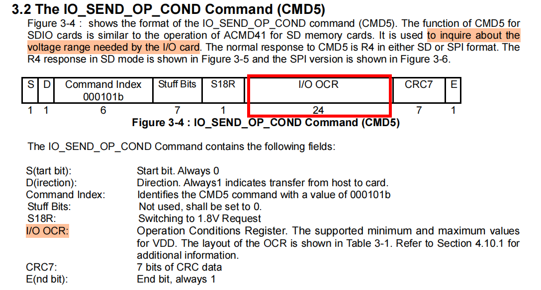
mmc_send_io_op_cond:CMD5命令
mmc_send_io_op_cond执行的操作,就是host端向device端发送一个 CMD5,并根据返回的I/O OCR来设置合适的电压。
CMD5的命令格式如下:
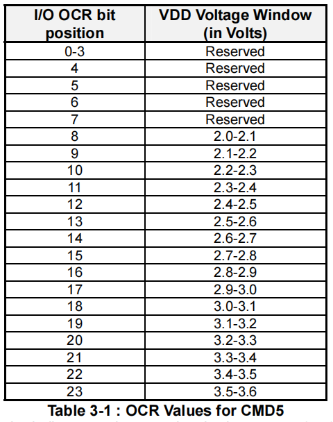
I/O OCR的bit值与电压值的匹配表格如下:
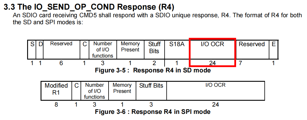
CMD5的R4 回复格式如下:
3. SDIO命令协议
SDIO卡协议中最主要的就是CMD52和CMD53,核心区别如下:
| 特性 | CMD52 | CMD53 |
|---|---|---|
| 传输粒度 | 单字节 | 多字节/多块 |
| 数据线占用 | 不使用DAT线 | 使用DAT线 |
| 响应机制 | 有响应 | 无响应,需主动查询或中断 |
| 性能 | 适合小数据量快速操作 | 适合大数据量批量传输 |
| 应用场景 | 设备配置、状态查询 | 数据传输、文件读写 |
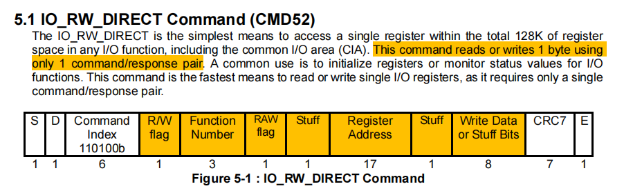
3.1 CMD52
CMD52命令用于对SDIO设备进行单字节级别的寄存器读写操作,适合快速配置设备或查询状态。每次只能读写一个字节,只使用CMD命令线,不占用数据线。命令格式如下:
这里调用的读写接口函数是sdio_readb或者sdio_writeb,再往下看,mmc中执行CMD52读写的函数是mmc_io_rw_direct_host,平时调试过程,可以把这个函数中的cmd的各个参数打印出来,再结合逻辑分析仪一起比对问题。
static int mmc_io_rw_direct_host(struct mmc_host *host, int write, unsigned fn,
	unsigned addr, u8 in, u8 *out)

	struct mmc_command cmd = {};
	int err;

	if (fn > 7)
		return -EINVAL;

	/* sanity check */
	if (addr & ~0x1FFFF)
		return -EINVAL;

	cmd.opcode = SD_IO_RW_DIRECT;  // 52命令头
	cmd.arg = write ? 0x80000000 : 0x00000000;  // 读写标志位
	cmd.arg |= fn << 28;  // 功能号
	cmd.arg |= (write && out) ? 0x08000000 : 0x00000000;  // 写后读”(Read after Write)标志
	cmd.arg |= addr << 9;  // 需要操作的寄存器地址
	cmd.arg |= in;  // 写操作的具体的单字节的值;如果是读操作,就置零
	cmd.flags = MMC_RSP_SPI_R5 | MMC_RSP_R5 | MMC_CMD_AC; // host需要提供针对MMC卡、SD 卡和SDIO卡的SPI响应类型

	err = mmc_wait_for_cmd(host, &cmd, 0);
	if (err)
		return err;

	if (mmc_host_is_spi(host)) {
		/* host driver already reported errors */
	} else {
		if (cmd.resp[0] & R5_ERROR)
			return -EIO;
		if (cmd.resp[0] & R5_FUNCTION_NUMBER)
			return -EINVAL;
		if (cmd.resp[0] & R5_OUT_OF_RANGE)
			return -ERANGE;
	}

	if (out) {
		if (mmc_host_is_spi(host))
			*out = (cmd.resp[0] >> 8) & 0xFF;
		else
			*out = cmd.resp[0] & 0xFF;
	}

	return 0;
}
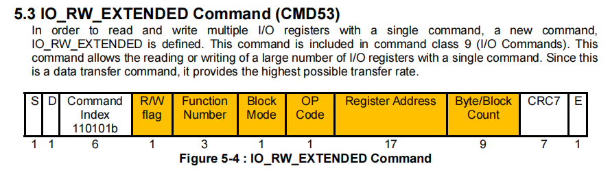
3.2 CMD53
CMD53命令是对CMD52的扩展,支持多字节或多块的批量数据传输,适合大量数据交换,可以传输1-512字节的任意长度数据。命令格式如下:
这里调用的读写接口函数是sdio_memcpy_fromio,然后调用的是 sdio_io_rw_ext_helper,在这里面会判断,这条命令是使用字节模式或者是快模式进行传输。
- 块模式:根据cmd中的blocks和blksz参数,来对数据包进行拆分。比如如果blksz = 512,那么传输一个480字节的数据包,就会被分成1个块来做传输;而传输一个900字节的数据包,就会被拆分为两个块来做传输。
- 字节模式:传输1 到 512 个字节之间的任意长度,数据长度不固定、零散的小数据包传输。
/* Split an arbitrarily sized data transfer into several
  * IO_RW_EXTENDED commands. */
static int sdio_io_rw_ext_helper(struct sdio_func *func, int write,
	unsigned addr, int incr_addr, u8 *buf, unsigned size)
{
	~~~ ~~~
	/* 块模式读写:根据cmd中的blocks和blksz参数,拆分数据包*/
	if (func->card->cccr.multi_block && (size > sdio_max_byte_size(func))) {
		/* Blocks per command is limited by host count, host transfer
		 * size and the maximum for IO_RW_EXTENDED of 511 blocks. */
		max_blocks = min(func->card->host->max_blk_count, 511u);

		while (remainder >= func->cur_blksize) {
			unsigned blocks;

			blocks = remainder / func->cur_blksize;
			if (blocks > max_blocks)
				blocks = max_blocks;
			size = blocks * func->cur_blksize;

			ret = mmc_io_rw_extended(func->card, write,
				func->num, addr, incr_addr, buf,
				blocks, func->cur_blksize);
			if (ret)
				return ret;

			remainder -= size;
			buf += size;
			if (incr_addr)
				addr += size;
		}
	}

	/* 字节模式:传输1到512个字节之间的任意长度 */
	while (remainder > 0) {
		size = min(remainder, sdio_max_byte_size(func));

		/* Indicate byte mode by setting "blocks" = 0 */
		ret = mmc_io_rw_extended(func->card, write, func->num, addr,
			 incr_addr, buf, 0, size);
		if (ret)
			return ret;

		remainder -= size;
		buf += size;
		if (incr_addr)
			addr += size;
	}
	return 0;
}
然后mmc层所调用的发送命令,一个关键函数是mmc_io_rw_extended,在这里面,会对cmd的各个参数做最后一步处理。正常情况下,这里发出的命令跟device端收到的命令应该是一模一样的。所以如果遇到问题,在这个函数中把cmd的各个参数打印出来,并与逻辑分析仪的波形做比对,也是一种常用的分析方法。
int mmc_io_rw_extended(struct mmc_card *card, int write, unsigned fn,
	unsigned addr, int incr_addr, u8 *buf, unsigned blocks, unsigned blksz)
{
	~~~~~~
	mrq.cmd = &cmd;
	mrq.data = &data;

	cmd.opcode = SD_IO_RW_EXTENDED;  // 53命令
	cmd.arg = write ? 0x80000000 : 0x00000000;  // 读写标志位
	cmd.arg |= fn << 28;  // 功能号
	cmd.arg |= incr_addr ? 0x04000000 : 0x00000000;  // 判断是使用增量地址模式,或者是固定地址模式
	cmd.arg |= addr << 9;  // 需要操作的寄存器地址
	if (blocks == 0)
		cmd.arg |= (blksz == 512) ? 0 : blksz;	/* byte mode */
	else
		cmd.arg |= 0x08000000 | blocks;		/* block mode */
	cmd.flags = MMC_RSP_SPI_R5 | MMC_RSP_R5 | MMC_CMD_ADTC;

	data.blksz = blksz;
	/* Code in host drivers/fwk assumes that "blocks" always is >=1 */
	data.blocks = blocks ? blocks : 1;
	data.flags = write ? MMC_DATA_WRITE : MMC_DATA_READ;

	left_size = data.blksz * data.blocks;
	nents = DIV_ROUND_UP(left_size, seg_size);
	if (nents > 1) {
		if (sg_alloc_table(&sgtable, nents, GFP_KERNEL))
			return -ENOMEM;

		data.sg = sgtable.sgl;
		data.sg_len = nents;

		for_each_sg(data.sg, sg_ptr, data.sg_len, i) {
			sg_set_buf(sg_ptr, buf + i * seg_size,
				   min(seg_size, left_size));
			left_size -= seg_size;
		}
	} else {
		data.sg = &sg;
		data.sg_len = 1;

		sg_init_one(&sg, buf, left_size);
	}

	mmc_set_data_timeout(&data, card);

	mmc_pre_req(card->host, &mrq);

	mmc_wait_for_req(card->host, &mrq);

	~~~ ~~~
}
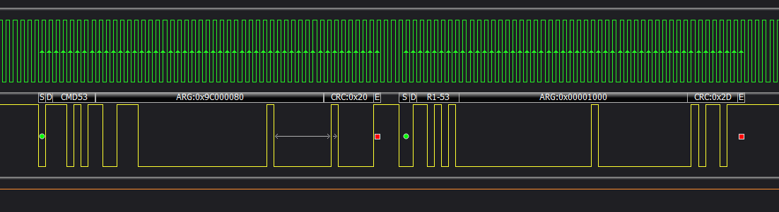
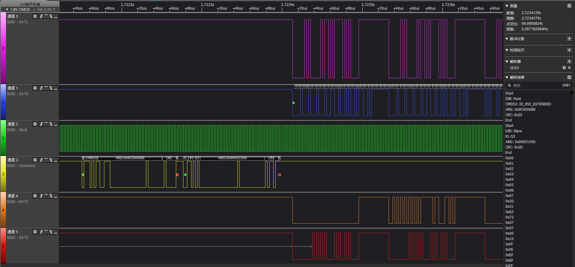
附上一张逻辑分析仪抓到的CMD53的命令,开头是cmd数据线的内容,cmd结束后,就是四根data线做数据传输:
4. SDIO中断
为了让SDIO卡能够中断主机,SD接口的一个引脚上添加了中断功能。在4位SD模式下用作DAT[1]的8号引脚,用于向主机发送卡的中断信号。中断的使用对每张卡或卡内的每个功能是可选的。
一旦发出中断信号,在中断原因消除或主机发出释放命令前,该模块不得停止中断信号。由于仅存在1条中断线,其可能被多个中断源共享。功能模块将持续发送中断信号,直至主机响应并清除中断。
SDIO功能通过CCCR寄存器中的两个比特位实现此机制:中断使能位和中断挂起位。每个可生成中断的功能模块均有一个中断使能位。此外,SDIO卡还设有主中断使能位以控制所有功能模块。仅当功能模块使能位和卡的主使能位同时置位时,中断信号才会传输至SD总线。第二个中断相关比特位称为中断挂起位,该只读位用于向主机指示哪些功能模块可能正在请求中断。每个可生成中断的功能模块均对应一个中断挂起位。
SDIO的中断函数实现,源码在kernel_platform/common/drivers/mmc/core/sdio_irq.c
作为外围的SDIO设备驱动,如果需要使用SDIO的中断,可以直接调用sdio_claim_irq函数。
/**
* sdio_claim_irq - claim the IRQ for a SDIO function
* @func: SDIO function
* @handler: IRQ handler callback
*
* Claim and activate the IRQ for the given SDIO function. The provided
* handler will be called when that IRQ is asserted. The host is always
* claimed already when the handler is called so the handler should not
* call sdio_claim_host() or sdio_release_host().
*/
int sdio_claim_irq(struct sdio_func *func, sdio_irq_handler_t *handler)
{
int ret;
unsigned char reg;
if (!func)
return -EINVAL;
pr_debug("SDIO: Enabling IRQ for %s...\n", sdio_func_id(func));
if (func->irq_handler) {
pr_debug("SDIO: IRQ for %s already in use.\n", sdio_func_id(func));
return -EBUSY;
}
/* 读取卡内中断寄存器SDIO_CCCR_IENx的值 */
ret = mmc_io_rw_direct(func->card, 0, 0, SDIO_CCCR_IENx, 0, ®);
if (ret)
return ret;
reg |= 1 << func->num;
reg |= 1; /* Master interrupt enable */
/* 往卡内的中断寄存器SDIO_CCCR_IENx中写'1',也就是使能卡中断 */
ret = mmc_io_rw_direct(func->card, 1, 0, SDIO_CCCR_IENx, reg, NULL);
if (ret)
return ret;
func->irq_handler = handler;
/* 获取SDIO卡的中断线程处理函数,这个是我们自己传进来的 */
ret = sdio_card_irq_get(func->card);
if (ret)
func->irq_handler = NULL;
/* 将中断处理函数与中断信号来绑定 */
sdio_single_irq_set(func->card);
return ret;
}
EXPORT_SYMBOL_GPL(sdio_claim_irq);
具体关于SDIO中断的使用,可以看下cw1200的WiFi驱动中对于SDIO中断的使用示例:
不过在中断处理函数中,一般建议只放一些非延时的操作函数,用于快速响应;如果一些耗时长的行为,需要由中断函数申请注册一个线程,将耗时行为放到线程中去进行。
static void cw1200_sdio_irq_handler(struct sdio_func *func)
{
    /* 具体中断处理函数 */
	struct hwbus_priv *self = sdio_get_drvdata(func);

	/* note:  sdio_host already claimed here. */
	if (self->core)
		cw1200_irq_handler(self->core);
}

static int cw1200_sdio_irq_subscribe(struct hwbus_priv *self)
{
	int ret = 0;

	pr_debug("SW IRQ subscribe\n");
	sdio_claim_host(self->func);
	if (self->pdata->irq)
		ret = cw1200_request_irq(self);
	else
        /* 注册SDIO中断,中断处理函数为cw1200_sdio_irq_handler */
		ret = sdio_claim_irq(self->func, cw1200_sdio_irq_handler);

	sdio_release_host(self->func);
	return ret;
}
其他链接资料
MMC子系统:
https://blog.youkuaiyun.com/gy794627991/article/details/140629540
SDIO协议:
https://blog.youkuaiyun.com/weixin_49259827/article/details/136632127
https://2048ai.net/68254ebfa5baf817cf4c0e21.html
SDIO卡的识别流程:
https://zhuanlan.zhihu.com/p/147192078
https://zhuanlan.zhihu.com/p/147192949
SDIO中断:
https://zhuanlan.zhihu.com/p/5805587812


 599
599

 被折叠的 条评论
为什么被折叠?
被折叠的 条评论
为什么被折叠?
 到【灌水乐园】发言


