


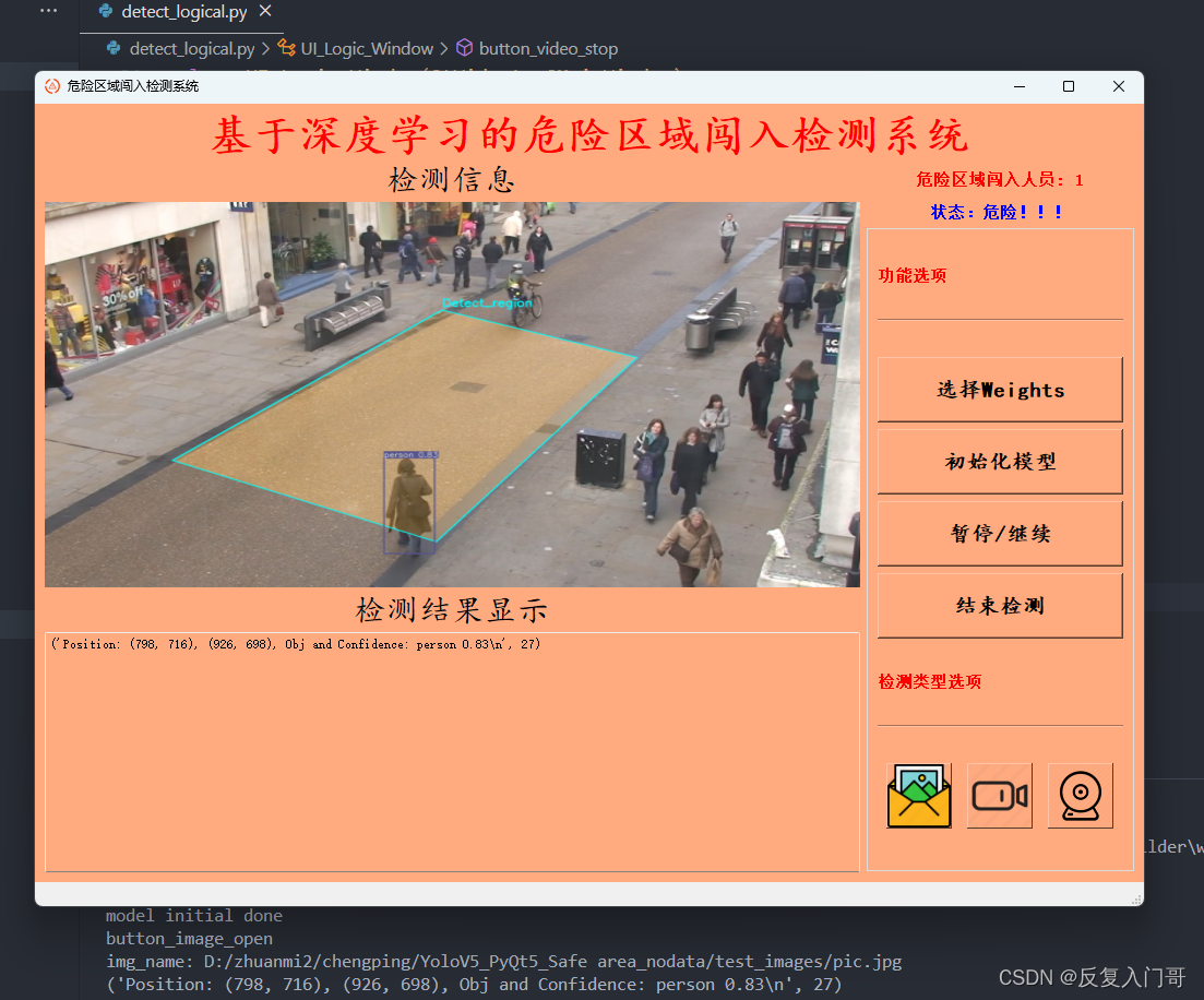
基于yolov5的危险区域闯入检测系统(UI界面,Python代码)
1.1 YOLOv5算法简介
YOLOv5是一种单阶段目标检测算法,该算法在YOLOv4的基础上添加了一些新的改进思路,使其 速度与精度都得到了极大的性能提升。主要的改进思路如下所示:
- 输入端:在模型训练阶段,提出了一些改进思路,主要包括Mosaic数据增强、自适应锚框计算、
自适应图片缩放; - 基准网络:融合其它检测算法中的一些新思路,主要包括:Focus结构与CSP结构;
- Neck网络:目标检测网络在BackBone与最后的Head输出层之间往往会插入一些层,Yolov5中添
加了FPN+PAN结构; - Head输出层:输出层的锚框机制与YOLOv4相同,主要改进的是训练时的损失函数GIOU_Loss,
以及预测框筛选的DIOU_nms
1.2 YOLOv5网络架构
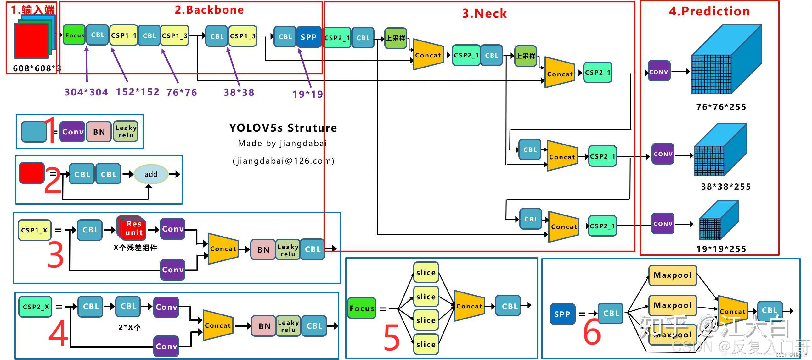
上图展示了YOLOv5目标检测算法的整体框图。对于一个目标检测算法而言,我们通常可以将其划 分为4个通用的模块,具体包括:输入端、基准网络、 Neck网络与Head输出端,对应于上图中的4个红 色模块。 YOLOv5算法具有4个版本,具体包括: YOLOv5s、YOLOv5m、YOLOv5l、YOLOv5x四种,本 文重点讲解YOLOv5s,其它的版本都在该版本的基础上对网络进行加深与加宽。
-
输入端: 输入端表示输入的图片。该网络的输入图像大小为608*608,该阶段通常包含一个图像预处理阶段,即将输入图像缩放到网络的输入大小,并进行归一化等操作。
-
在网络训练阶段: YOLOv5使用Mosaic数据增强操作提升模型的训练速度和网络的精度;并提出了一种自适应锚框计算与自适应图片缩放方法。
-
基准网络: 基准网络通常是一些性能优异的分类器种的网络,该模块用来提取一些通用的特征表示。 YOLOv5中不仅使用了CSPDarknet53结构,而且使用了Focus结构作为基准网络。
-
Neck网络: Neck网络通常位于基准网络和头网络的中间位置,利用它可以进一步提升特征的多样性及鲁棒性。虽然YOLOv5同样用到了SPP模块、
FPN+PAN模块,但是实现的细节有些不同。 -
Head输出层: Head用来完成目标检测结果的输出。针对不同的检测算法,输出端的分支个数不尽相同,通常包含一个分类分支和一个回归分支。
YOLOv4利用GIOU_Loss来代替Smooth L1 Loss函数,从而进一步提升算法的检测精度。
1.3 yolo5指定检测区域
1.3.1、确定检测范围
快捷查询方法:
用windows自带画图打开图片
鼠标移到想要框选检测区域的四个顶点,查询点的像素坐标
分别计算点的像素坐标与图片总像素坐标的比例(后面要用)
查询方法如下图所示:
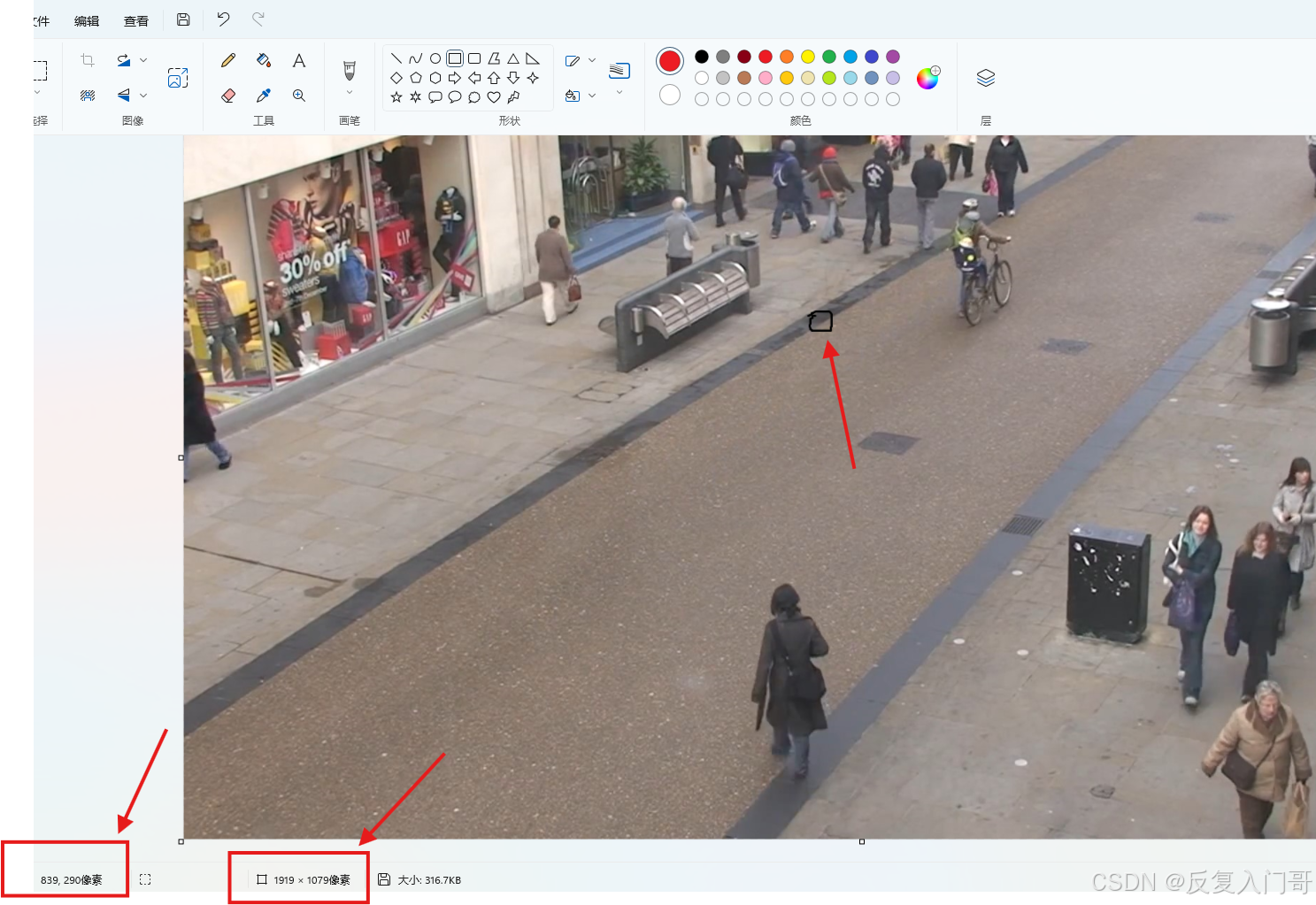 例如:图中所标注的点(839,290)代表(x,y)坐标
hl1 = 290/ 1079 (可约分)监测区域纵坐标距离图片顶部 比例
wl1 = 839 / 1919 (可约分)监测区域横坐标距离图片左部 比例
这里只举例了一个点,如检测范围是四边形,需要计算左上,右上,右下,左下四个顶点。
1.3.2 确定区域检测范围
在detect中插入以下代码:
        # mask for certain region
        #1,2,3,4 分别对应左上,右上,右下,左下四个点
        hl1 = 302 / 1080 #监测区域高度距离图片顶部比例
        wl1 = 935 / 1920 #监测区域高度距离图片左部比例
        hl2 = 435 / 1080  # 监测区域高度距离图片顶部比例
        wl2 = 1394 / 1920  # 监测区域高度距离图片左部比例
        hl3 = 951 / 1080  # 监测区域高度距离图片顶部比例
        wl3 = 921 / 1920  # 监测区域高度距离图片左部比例
        hl4 = 723 / 1080  # 监测区域高度距离图片顶部比例
        wl4 = 300 / 1920  # 监测区域高度距离图片左部比例
        if webcam:
            for b in range(0,img.shape[0]):
                mask = np.zeros([img[b].shape[1], img[b].shape[2]], dtype=np.uint8)
                #mask[round(img[b].shape[1] * hl1):img[b].shape[1], round(img[b].shape[2] * wl1):img[b].shape[2]] = 255
                pts = np.array([[int(img[b].shape[2] * wl1), int(img[b].shape[1] * hl1)],  # pts1
                                [int(img[b].shape[2] * wl2), int(img[b].shape[1] * hl2)],  # pts2
                                [int(img[b].shape[2] * wl3), int(img[b].shape[1] * hl3)],  # pts3
                                [int(img[b].shape[2] * wl4), int(img[b].shape[1] * hl4)]], np.int32)
                mask = cv2.fillPoly(mask,[pts],(255,255,255))
                imgc = img[b].transpose((1, 2, 0))
                imgc = cv2.add(imgc, np.zeros(np.shape(imgc), dtype=np.uint8), mask=mask)
                #cv2.imshow('1',imgc)
                img[b] = imgc.transpose((2, 0, 1))

        else:
            mask = np.zeros([img.shape[1], img.shape[2]], dtype=np.uint8)
            #mask[round(img.shape[1] * hl1):img.shape[1], round(img.shape[2] * wl1):img.shape[2]] = 255
            pts = np.array([[int(img.shape[2] * wl1), int(img.shape[1] * hl1)],  # pts1
                            [int(img.shape[2] * wl2), int(img.shape[1] * hl2)],  # pts2
                            [int(img.shape[2] * wl3), int(img.shape[1] * hl3)],  # pts3
                            [int(img.shape[2] * wl4), int(img.shape[1] * hl4)]], np.int32)
            mask = cv2.fillPoly(mask, [pts], (255,255,255))
            img = img.transpose((1, 2, 0))
            img = cv2.add(img, np.zeros(np.shape(img), dtype=np.uint8), mask=mask)
            img = img.transpose((2, 0, 1))
1.3.3 画检测区域线
            if webcam:  # batch_size >= 1
                p, s, im0, frame = path[i], f'{i}: ', im0s[i].copy(), dataset.count
                cv2.putText(im0, "Detection_Region", (int(im0.shape[1] * wl1 - 5), int(im0.shape[0] * hl1 - 5)),
                            cv2.FONT_HERSHEY_SIMPLEX,
                            1.0, (255, 255, 0), 2, cv2.LINE_AA)

                pts = np.array([[int(im0.shape[1] * wl1), int(im0.shape[0] * hl1)],  # pts1
                                [int(im0.shape[1] * wl2), int(im0.shape[0] * hl2)],  # pts2
                                [int(im0.shape[1] * wl3), int(im0.shape[0] * hl3)],  # pts3
                                [int(im0.shape[1] * wl4), int(im0.shape[0] * hl4)]], np.int32)  # pts4
                # pts = pts.reshape((-1, 1, 2))
                zeros = np.zeros((im0.shape), dtype=np.uint8)
                mask = cv2.fillPoly(zeros, [pts], color=(0, 165, 255))
                im0 = cv2.addWeighted(im0, 1, mask, 0.2, 0)
                cv2.polylines(im0, [pts], True, (255, 255, 0), 3)
                # plot_one_box(dr, im0, label='Detection_Region', color=(0, 255, 0), line_thickness=2)
            else:
                p, s, im0, frame = path, '', im0s.copy(), getattr(dataset, 'frame', 0)
                cv2.putText(im0, "Detection_Region", (int(im0.shape[1] * wl1 - 5), int(im0.shape[0] * hl1 - 5)),
                            cv2.FONT_HERSHEY_SIMPLEX,
                            1.0, (255, 255, 0), 2, cv2.LINE_AA)
                pts = np.array([[int(im0.shape[1] * wl1), int(im0.shape[0] * hl1)],  # pts1
                                [int(im0.shape[1] * wl2), int(im0.shape[0] * hl2)],  # pts2
                                [int(im0.shape[1] * wl3), int(im0.shape[0] * hl3)],  # pts3
                                [int(im0.shape[1] * wl4), int(im0.shape[0] * hl4)]], np.int32)  # pts4
                # pts = pts.reshape((-1, 1, 2))
                zeros = np.zeros((im0.shape), dtype=np.uint8)
                mask = cv2.fillPoly(zeros, [pts], color=(0, 165, 255))
                im0 = cv2.addWeighted(im0, 1, mask, 0.2, 0)

                cv2.polylines(im0, [pts], True, (255, 255, 0), 3)
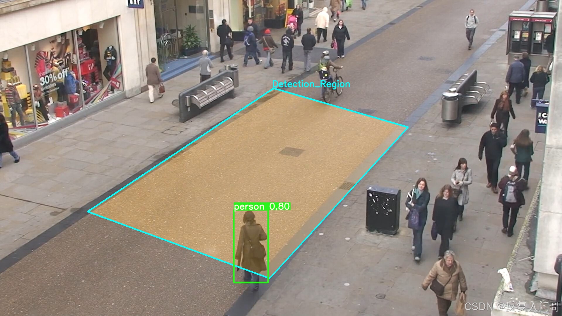
1.3.4 效果展示
总结
基于yolov5的区域目标检测实质上就是在图片选定检测区域做一个遮掩mask,检测区域不一定为四边形,也可是其他形状。该方法可检测图片/视频/摄像头。
其他
私信作者可获取完整yolo5+pyqt源码!
或者点击链接直接获取:链接


 685
685

 被折叠的 条评论
为什么被折叠?
被折叠的 条评论
为什么被折叠?
 到【灌水乐园】发言


