【微知】如何快速查看Mellanox网卡的config中某个config的作用?(mlxconfig -d 01:00.0 show_confs; mlxconfig -d 01:00.0 i)

背景

经常需要使用mlxconfig来配置某个静态参数。 这些配置的作用mlxconfig提供了一个命令来查看作用

命令

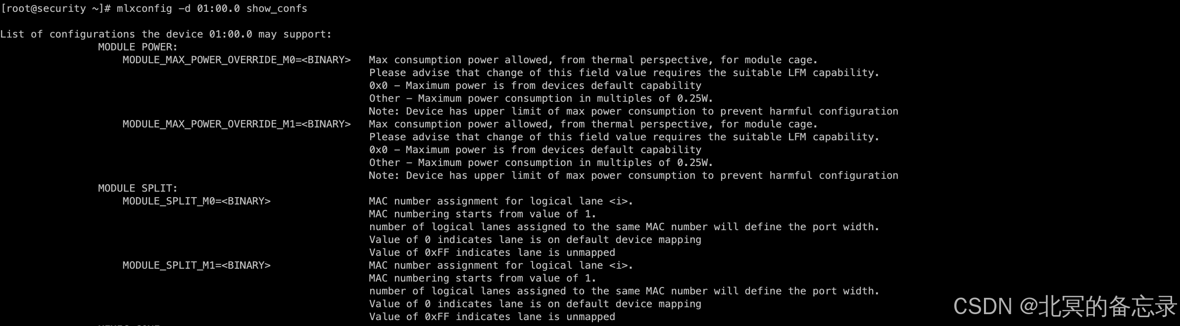
mlxconfig -d 01:00.0 show_confs # 查看config
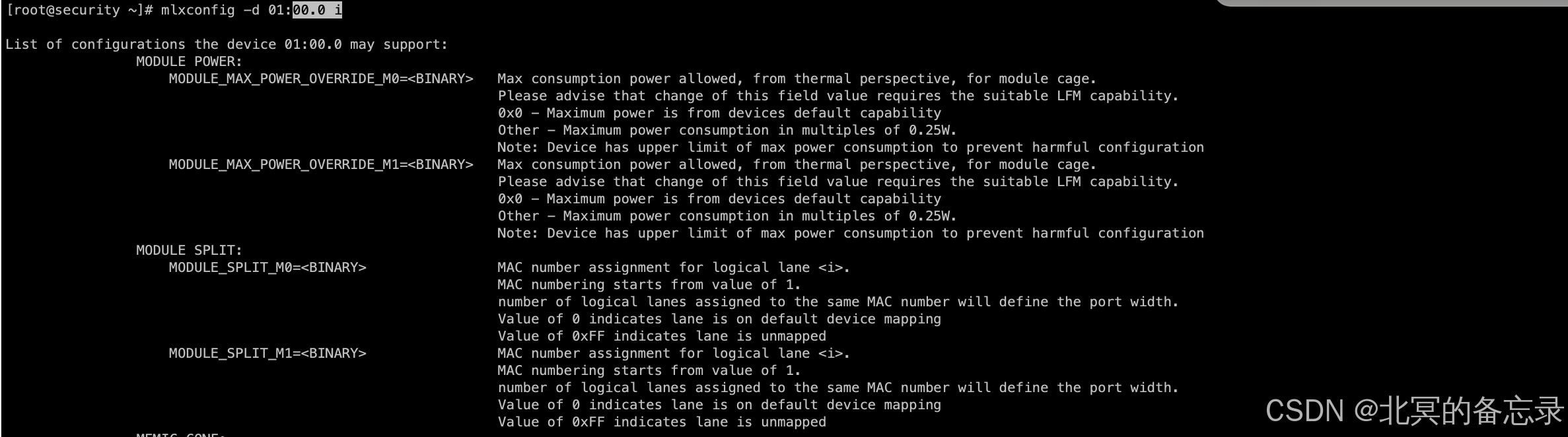
mlxconfig -d 01:00.0 i #简洁方法
mlxconfig -d 01:00.0 i | grep SRIOV_EN # 只查看某个配置的作用

在这里插入图片描述

实操

查看某个配置

在这里插入图片描述

查看全量配置

i方式

在这里插入图片描述

show_confs方式

在这里插入图片描述

全量mlxconfig可供查询的配置

当前是基于cx5的信息

[root@security ~]# mlxconfig -d 01:00.0 i 

List of configurations the device 01:00.0 may support:
                MODULE POWER:
                    MODULE_MAX_POWER_OVERRIDE_M0=<BINARY>   Max consumption power allowed, from thermal perspective, for module cage.
                                                            Please advise that change of this field value requires the suitable LFM capability.
                                                            0x0 - Maximum power is from devices default capability
                                                            Other - Maximum power consumption in multiples of 0.25W.
                                                            Note: Device has upper limit of max power consumption to prevent harmful configuration
                    MODULE_MAX_POWER_OVERRIDE_M1=<BINARY>   Max consumption power allowed, from thermal perspective, for module cage.
                                                            Please advise that change of this field value requires the suitable LFM capability.
                                                            0x0 - Maximum power is from devices default capability
                                                            Other - Maximum power consumption in multiples of 0.25W.
                                                            Note: Device has upper limit of max power consumption to prevent harmful configuration
                MODULE SPLIT:
                    MODULE_SPLIT_M0=<BINARY>                MAC number assignment for logical lane <i>.
                                                            MAC numbering starts from value of 1.
                                                            number of logical lanes assigned to the same MAC number will define the port width.
                                                            Value of 0 indicates lane is on default device mapping
                                                            Value of 0xFF indicates lane is unmapped
                    MODULE_SPLIT_M1=<BINARY>                MAC number assignment for logical lane <i>.
                                                            MAC numbering starts from value of 1.
                                                            number of logical lanes assigned to the same MAC number will define the port width.
                                                            Value of 0 indicates lane is on default device mapping
                                                            Value of 0xFF indicates lane is unmapped
                MEMIC CONF:
                    MEMIC_ATOMIC=<DEVICE_DEFAULT|MEMIC_ATOMIC_DISABLE|MEMIC_ATOMIC_ENABLE>Indicates whether Atomic operations address range is supported for MEMIC. When accessing this range Read and Write operation are translated into 'Atomic test-and-set' and 'Atomic add' respectively.
                                                            0x0: DEVICE_DEFAULT
                                                            0x1: MEMIC_ATOMIC_DISABLE
                                                            0x2: MEMIC_ATOMIC_ENABLE
                                                            other values are reserved
                    MEMIC_ATOMIC_ENDIANESS=<DEVICE_DEFAULT|MEMIC_ATOMIC_ENDIANNESS_BIG|MEMIC_ATOMIC_ENDIANNESS_LITTLE>Indicates what is the endianness of MEMIC for DM operations. 
                                                            This configuration does not apply to Internal CPU.
                                                            0x0: DEVICE_DEFAULT
                                                            0x1: MEMIC_ATOMIC_ENDIANNESS_BIG
                                                            0x2: MEMIC_ATOMIC_ENDIANNESS_LITTLE
                    MEMIC_BAR_SIZE=<NUM>                    The amount of BAR size assigned for MEMIC. The size in bytes is memic_size_limit*2^log_memic_bar_size.
                                                            When activating MEMIC Atomic access by MEMIC_ATOMIC, the allocated BAR size for MEMIC is doubled.
                    MEMIC_SIZE_LIMIT=<DISABLED|_1024KB|_256KB|_512KB>The maximum amount of internal device memory that can be consumed by the MEMIC application.
                                                            0x0: DISABLED
                                                            0x1: _256KB
                                                            0x2: _512KB
                                                            0x3: _1024KB
                HOST CHAINING CONF:
                    HOST_CHAINING_CACHE_DISABLE=<False|True>When TRUE, host chaining data is not cached on the device.
                    HOST_CHAINING_DESCRIPTORS=<NUM>         Log(base 2) of the number of packets descriptors that should be allocated by the host for host chaining for a given IEEE802.1p priority i.
                                                            0 means that no descriptors are allocated for this priority and traffic with this priority will be dropped.
                    HOST_CHAINING_MODE=<BASIC|DISABLED>     Enable and select host-chaining mode.
                                                            0x0: DISABLED
                                                            0x1: BASIC
                                                            other values are reserved
                    HOST_CHAINING_TOTAL_BUFFER_SIZE=<NUM>   Log(base 2) of the buffer size (in bytes) allocated for host chaining for a given IEEE802.1p priority i.
                                                            0 means no buffer for this priority and traffic with this priority will be dropped.
                FPGA CONF:
                    FPGA_AUTO_RELOAD=<False|True>           When set, the FPGA bitstream is reloaded from flash as part of the ConnectX boot sequence.
                INTERNAL CPU CONF:
                    INTERNAL_CPU_ESWITCH_MANAGER=<ECPF|EXT_HOST_PF>Defines the owner of Eth Embedded Switch responsibilities
                                                            0x0: ECPF
                                                            0x1: EXT_HOST_PF
                                                            Valid for INTERNAL_CPU_MODEL = EMBEDDED_CPU
                                                            
                    INTERNAL_CPU_IB_VPORT0=<ECPF|EXT_HOST_PF>Defines the owner of IB Vport0 responsibilities
                                                            0x0: ECPF
                                                            0x1: EXT_HOST_PF
                                                            
                    INTERNAL_CPU_MODEL=<EMBEDDED_CPU|SEPARATED_HOST>Select the model for the Internal CPU
                                                            0x0: SEPARATED_HOST - Supported only when NV_INTERNAL_CPU_CAP.separate_host_model_supported==1.
                                                            0x1: EMBEDDED_CPU - Supported only when NV_INTERNAL_CPU_CAP.embedded_cpu_model_supported==1.
                                                            other values are reserved
                                                            This NVCONFIG parameter can only be configured from the embedded CPU.
                    INTERNAL_CPU_OFFLOAD_ENGINE=<DISABLED|ENABLED>Defines whether the Internal CPU is used as an offload engine
                                                            0x0: ENABLED
                                                            0x1: DISABLED
                                                            Valid for INTERNAL_CPU_MODEL = EMBEDDED_CPU
                                                            
                    INTERNAL_CPU_PAGE_SUPPLIER=<ECPF|EXT_HOST_PF>Defines the owner of providing ICM pages to the external host functions
                                                            0x0: ECPF
                                                            0x1: EXT_HOST_PF
                                                            Valid for INTERNAL_CPU_MODEL = EMBEDDED_CPU
                                                            
                FLEX PARSER CONF:
                    FLEX_IPV4_OVER_VXLAN_PORT=<NUM>         The UDP port for incoming IPoVxLAN traffic (non-standard).
                                                            When set, also affects flex_vxlan_gpe_supported when enabled on same profile.
                                                            
                    FLEX_PARSER_PROFILE_ENABLE=<NUM>        Indicates which flex parser profile to enable. Each profile supports a set of protocols. The support indication and the set of protocols supported by profile 'x' reported in NC_FLEX_PARSER_CAP.flex_parser_profile_x_supported.
                    PROG_PARSE_GRAPH=<False|True>           When TRUE, the device parse graph may be dynamically configured. The amount of programmable resources is reduced according to the amount of protocols already supported by FLEX_PARSER_PROFILE_ENABLE.
                ROCE 1 5 CONF:
                    ROCE_NEXT_PROTOCOL=<NUM>                The next protocol value set in the IPv4/IPv6 packets for RoCE v1.5.
                INTERNAL HAIRPIN CONF:
                    ESWITCH_HAIRPIN_DESCRIPTORS=<NUM>       Log(base 2) of the number of packets descriptors allocated internally for hairpin for a given IEEE802.1p priority i.
                                                            0 means that no descriptors are allocated for this priority and traffic with this priority will be dropped.
                    ESWITCH_HAIRPIN_TOT_BUFFER_SIZE=<NUM>   Log(base 2) of the buffer size (in bytes) allocated internally for hairpin for a given IEEE802.1p priority i.
                                                            0 means no buffer for this priority and traffic with this priority will be dropped.
                DPA AUTH:
                    DPA_AUTHENTICATION=<False|True>         When TRUE, DPA code is authenticated before executed.
                GLOBAL PCI CONF:
                    DPU_RESET_NOTIFICATION_ENABLED=<DISABLED|ENABLED>When set, the NIC can report PCIe errors through AER cap to all hosts it is connected to on DPU reset\panic. (If no error reporting is enabled, the DPU will not report any error.)
                                                            0x0: DISABLED
                                                            0x1: ENABLED
                    FPP_EN=<False|True>                     When this bit is cleared, the device exposes a single PCI function for both ports. When set, the device exposes one or more PCI functions for each port (this is the only mode supported by ConnectX-4 devices).
                    HIDE_PORT2_PF=<False|True>              When TRUE, the device will not advertise the PFs associated with port 2, except for the Embedded CPU (ECPF) if exists. This configuration is available only when NV_PCI_CONF.ADVANCED_PCI_SETTINGS is TRUE.
                    INTERNAL_CPU_RSHIM=<DISABLED|ENABLED>   Defines whether an RSHIM function will be exposed (when available) to the external host.
                                                            0x0: ENABLED
                                                            0x1: DISABLED
                                                            
                    NON_PREFETCHABLE_PF_BAR=<False|True>    When set, the PF BAR prefetchable bit is cleared.
                                                            Note: PCI switches and operation systems have dedicated quotas for non-prefetchable memory, hence, you may need to decrease log_pf_uar_bar_size to enable this feature.
                    NUM_OF_PF=<NUM>                         Total number of Network PCIe functions (PFs) exposed by the device. In case the number of PFs cannot be equally distributed between the number of ports, the remainder of PFs will be distribute between the ports with the lower numbers. For a Multi-Host device, this number is applied to each host individually.
                                                            Value 0 is only supported when an Emulated PCI Switch is present or another type of PF (e.g. emulated device).
                    NUM_OF_VFS=<NUM>                        The total number of Virtual Functions (VFs) that can be supported, for each PF.
                                                            Valid when PF_NUM_OF_VF_VALID is FALSE
                    NUM_PF_MSIX=<NUM>                       Number of MSI-X vectors and EQs per PF.
                    NUM_PF_MSIX_VALID=<False|True>          When set, the num_pf_msix field is valid. 
                                                            When cleared, the number of PF MSI-X is defined by PER_PF_NUM_MSIX
                    NUM_VF_MSIX=<NUM>                       Number of MSI-X vectors and EQs per VF.
                    PARTIAL_WRITE_CACHE_MODE=<ADDRESS_BASED|DEVICE_DEFAULT|DISABLED|FUNCTION_BASED>Specifies the mode of operation for PCI write cache, for partial cacheline writes:
                                                            0x0: DEVICE_DEFAULT - device default configuration
                                                            0x1: DISABLED
                                                            0x2: FUNCTION_BASED
                                                            0x3: ADDRESS_BASED
                                                            other values are reserved
                    PER_PF_NUM_SF=<False|True>              When TRUE, the SFs configuration is defined by TOTAL_SF and SF_BAR_SIZE for each PF individually. In case they are not defined for a PF, device defaults are used. 
                                                            When FALSE, the SFs configuration is defined by device defaults.
                                                            Valid only when PF_BAR2_ENABLE is set to FALSE.
                    PER_PF_NUM_VF_MSIX=<False|True>         When set to TRUE, the VF MSI-X configuration is defined by NUM_VF_MSIX for each PF individually. In case they are not defined for a PF, device defaults are used for that PF.
                                                            When set to FALSE, the MSI-X configuration is defined by 
                                                            NUM_VF_MSIX for all PFs.
                    PF_BAR2_ENABLE=<False|True>             When TRUE, BAR2 is exposed on all external host PFs (but not on the embedded ARM PFs/ECPFs). The BAR2 size is defined by the log_pf_bar2_size.
                                                            When FALSE, the SFs and BAR2 configurations are defined by PER_PF_NUM_SF
                    PF_BAR2_SIZE=<NUM>                      Log (base 2) of the size of a PF's BAR2 size, given in MB.
                    PF_LOG_BAR_SIZE=<NUM>                   Log 2 of the size of a PF"s UAR BAR in MBs.
                    PF_NUM_OF_VF_VALID=<False|True>         When TRUE, the number of VFs is defined for each networking PF individually in PF_NUM_OF_VF. In case they are not defined for a PF, device defaults are used instead.
                                                            When FALSE, the number of VFs is defined symmetrically for all PFs by NUM_OF_VFS
                    PF_NUM_PF_MSIX_VALID=<False|True>       When TRUE, the MSI-X configuration is defined by PF_NUM_PF_MSIX for each PF individually. In case they are not defined for a PF, device defaults are used.
                                                            When FALSE, the MSI-X configuration is defined by device defaults
                                                            Valid only when NUM_PF_MSIX_VALID is set to FALSE.
                    SRIOV_EN=<False|True>                   Enable Single-Root I/O Virtualization (SR-IOV)
                    STRICT_VF_MSIX_NUM=<False|True>         When set to TRUE, num_vf_msix defines a strict number (no calculation and roundup).
                    VF_LOG_BAR_SIZE=<NUM>                   Log 2 of the size of a VF"s UAR BAR in MBs.
                    VF_NODNIC_ENABLE=<False|True>           When set to TRUE, VF has VSC Gateway exposed through PCI, and may access the NODNIC initialization segment
                    VF_VPD_ENABLE=<False|True>              When set, VPD Capability is exposed to Virtual Functions.
                TPT CONF:
                    INT_LOG_MAX_PAYLOAD_SIZE=<AUTOMATIC|_4KB>Sets the PCIe burst size for the NIC internal Translation and Protection (TPT) mechanism.
                                                            0x0: AUTOMATIC
                                                            0xC: _4KB
                GLOBAL PCI CONF 2:
                    MAX_ACC_OUT_READ=<NUM>                  Maximum accumulated outstanding Read requests bytes. Value is given in units of 1K bytes.
                                                            The limit is applied for each PCI bus link individually.
                                                            Value 0x0 indicates the use of device defaults.
                                                            Configuration is available only when NV_PCI_CONF.ADVANCED_PCI_SETTINGS is TRUE.
                    PCIE_CREDIT_TOKEN_TIMEOUT=<NUM>         PCIe credit timeout. In case a pending transaction has no credits longer than this timeout value, buffered transactions will be dropped. Value is given in milliseconds in the range of 10 to 4,000. 
                                                            Value 0x0 indicates the device will adjust the timeout automatically.
                                                            Value 0xffff disables the feature.
                                                            
                POWER CONF:
                    ACCURATE_TX_SCHEDULER=<False|True>      When TRUE, the device will optimize the transmit scheduler for high accuracy.
                                                            When False, the device defaults will apply for the scheduler.
                    ADVANCED_POWER_SETTINGS=<False|True>    Show/hide additional power settings parameters.
                                                            Warning: Wrong power settings may cause physical damage.
                    DISABLE_SLOT_POWER_LIMITER=<False|True> When cleared, the device is not allowed to consume more than 25W from the PCIe power rails, unless a PCI slot power limit message statesthat a new power limit is received.
                                                            When set, the slot power limiter is disabled, and the device is allowed to consume more than 25W from the PCIe power rails.
                                                            Note: if the power limiter is active and there is not enough power, the device will shut down the network modules.
                    LAG_RESOURCE_ALLOCATION=<DEVICE_DEFAULT|PRE_ALLOCATION>Defines the way resources are allocated for LAG
                                                            0x0: DEVICE_DEFAULT
                                                            0x1: PRE_ALLOCATION - resources are preallocated regardless of LAG activation
                                                            using pre-allocation allows LAG activation regardless of functions state
                                                            Other values are reserved
                    NETWORK_PORTS_NUMBER=<NUM>              Number of network ports enabled by the device, If the value exceeds the number of ports supported by the card, this field will be ignored. Value 0x0 indicates device defaults.
                    PARTIAL_RESET_EN=<False|True>           When set, the partial reset flow is enabled. This reset skips on resetting GPIOs, loading PLL new parameters and performing self-tests. Partial reset will be triggered only if no exceptions requiring full reset were detected (for example, if any of the boot record"s parameter had changed)
                    PHY_COUNT_LINK_UP_DELAY=<DELAY_10_SEC|DELAY_20_SEC|DELAY_NONE>Defines a period after Link UP where phy counters activation is delayed
                                                            0x0: DELAY_NONE
                                                            0x1: DELAY_10_SEC
                                                            0x2: DELAY_20_SEC
                                                            Other values are reserved
                    RESET_WITH_HOST_ON_ERRORS=<False|True>  When set, host reset will trigger a device reset, if the device has previously detected fatal errors.
                    RT_PPS_ENABLED_ON_POWERUP=<False|True>  When TRUE the PPS_OUT will be activated on power up
                                                            Applicable only when REAL_TIME_CLOCK_ENABLE is TRUE
                    SW_RECOVERY_ON_ERRORS=<False|True>      When set, SW will be instructed to perform a recovery flow when health buffer reports an error.
                HOST SYNC CONF:
                    ICMD_SEM_LOCK_THRESHOLD=<NUM>           Host will be expelled from VSEC Gateway usage if it holds the ICMD Global Semaphore for a period longer than this threshold. Value is given in units of 0.1sec
                                                            Value 0xFFFF indicates this threshold is infinite (disabled)
                    IDLE_ICMD_SEM_LOCK_THRESHOLD=<NUM>      Host will be expelled from VSEC Gateway usage if it holds the ICMD Global Semaphore, without issuing any ICMD, for a period longer than this threshold. Value is given in units of 0.1sec
                                                            Value 0xFFFF indicates this threshold is infinite (disabled)
                    VSEC_EXPULSION_DURATION=<NUM>           Host VSEC Gateway expulsion will persist for this period. Value is given in units of 0.1sec
                EMULATION NVME CONF:
                    NVME_EMULATION_CLASS_CODE=<NUM>         PCIe class_code register for the NVME emulated device
                    NVME_EMULATION_DEVICE_ID=<NUM>          PCIe device_id config register for the NVME emulated device.
                    NVME_EMULATION_ENABLE=<False|True>      When set to TRUE, NVME device emulation is enabled.
                    NVME_EMULATION_MAX_QUEUE_DEPTH=<NUM>    Log (base 2) of the maximal queue depth of NVME Physical Functions.
                                                            Value 0 indicates device default.
                    NVME_EMULATION_NUM_MSIX=<NUM>           Number of MSI-X Vectors assigned for each PF/VF of the NVME emulation device. Value 0x0 will use device defaults
                    NVME_EMULATION_NUM_PF=<NUM>             Total number of PCIe functions (PFs) exposed by the device for NVME emulation.
                    NVME_EMULATION_NUM_VF=<NUM>             The total number of Virtual Functions (VFs) that can be supported for each PF.
                    NVME_EMULATION_NUM_VF_MSIX=<NUM>        Number of MSI-X vectors assigned to each VF associated with this type of PF. Value 0x0 indicates device defaults.
                    NVME_EMULATION_REVISION_ID=<NUM>        PCIe revision_id register for the NVME emulated device
                    NVME_EMULATION_SUBSYSTEM_ID=<NUM>       PCIe subsystem_id register for the NVME emulated device
                    NVME_EMULATION_SUBSYSTEM_VENDOR_ID=<NUM>PCIe subsystem_vendor_id register for the NVME emulated device
                    NVME_EMULATION_VENDOR_ID=<NUM>          PCIe vendor_id config register for the NVME emulated device.
                EMULATION PCI SWITCH CONF:
                    PCI_SWITCH_EMULATION_ENABLE=<False|True>When TRUE, the device will expose a PCI switch. All PF configurations are applied on the switch downstream ports. On such case, each PF will have a different PCI device on the emulated switch. This configuration allows to expose 0 network PFs toward host
                    PCI_SWITCH_EMULATION_NUM_PORT=<NUM>     Number of emulated switch downstream ports. Each downstream port can hold either one emulated PCI hotplug PF or multiple PCI static PFs (emulated functions or Nvidia functions).
                    VIRTIO_EMULATION_HOTPLUG_TRANS=<False|True>When TRUE, the device will support hotplug of EMulated transitional VIRTIO devices
                EMULATION VIRTIO NET CONF:
                    VIRTIO_NET_EMULATION_ENABLE=<False|True>When set to TRUE, VIRTIO_NET device emulation is enabled.
                    VIRTIO_NET_EMULATION_NUM_MSIX=<NUM>     Number of MSI-X Vectors assigned for each PF/VF of the VIRTIO_NET emulation device. Value 0x0 will use device defaults
                    VIRTIO_NET_EMULATION_NUM_PF=<NUM>       Total number of PCIe functions (PFs) exposed by the device for VIRTIO_NET emulation.
                    VIRTIO_NET_EMULATION_NUM_VF=<NUM>       The total number of Virtual Functions (VFs) that can be supported for each PF.
                    VIRTIO_NET_EMULATION_NUM_VF_MSIX=<NUM>  Number of MSI-X vectors assigned to each VF associated with this type of PF. Value 0x0 indicates device defaults.
                    VIRTIO_NET_EMULATION_PF_PCI_LAYOUT=<VIRTIO_1_X|VIRTIO_TRANSITIONAL>Indicates which VIrtIO specification the PCI layout of the emulated Physical Function(s) will follow.
                                                            0x0: VIRTIO_1_X
                                                            0x1: VIRTIO_TRANSITIONAL
                                                            other values are reserved
                    VIRTIO_NET_EMULATION_SUBSYSTEM_ID=<NUM> PCIe subsystem_id register for the VIRTIO_NET emulated device
                    VIRTIO_NET_EMULATION_VF_PCI_LAYOUT=<VIRTIO_1_X|VIRTIO_TRANSITIONAL>Indicates which VIrtIO specification the PCI layout of the emulated Virtual Function(s) will follow.
                                                            0x0: VIRTIO_1_X
                                                            0x1: VIRTIO_TRANSITIONAL
                                                            other values are reserved
                    VIRTIO_NET_EMU_SUBSYSTEM_VENDOR_ID=<NUM>PCIe subsystem_vendor_id register for the VIRTIO_NET emulated device
                EMULATION VIRTIO BLK CONF:
                    VIRTIO_BLK_EMULATION_ENABLE=<False|True>When set to TRUE, VIRTIO_BLK device emulation is enabled.
                    VIRTIO_BLK_EMULATION_NUM_MSIX=<NUM>     Number of MSI-X Vectors assigned for each PF/VF of the VIRTIO_BLK emulation device. Value 0x0 will use device defaults
                    VIRTIO_BLK_EMULATION_NUM_PF=<NUM>       Total number of PCIe functions (PFs) exposed by the device for VIRTIO_BLK emulation.
                    VIRTIO_BLK_EMULATION_NUM_VF=<NUM>       The total number of Virtual Functions (VFs) that can be supported for each PF.
                    VIRTIO_BLK_EMULATION_NUM_VF_MSIX=<NUM>  Number of MSI-X vectors assigned to each VF associated with this type of PF. Value 0x0 indicates device defaults.
                    VIRTIO_BLK_EMULATION_PF_PCI_LAYOUT=<VIRTIO_1_X|VIRTIO_TRANSITIONAL>Indicates which VIrtIO specification the PCI layout of the emulated Physical Function(s) will follow.
                                                            0x0: VIRTIO_1_X
                                                            0x1: VIRTIO_TRANSITIONAL
                                                            other values are reserved
                    VIRTIO_BLK_EMULATION_SUBSYSTEM_ID=<NUM> PCIe subsystem_id register for the VIRTIO_BLK emulated device
                    VIRTIO_BLK_EMULATION_VF_PCI_LAYOUT=<VIRTIO_1_X|VIRTIO_TRANSITIONAL>Indicates which VIrtIO specification the PCI layout of the emulated Virtual Function(s) will follow.
                                                            0x0: VIRTIO_1_X
                                                            0x1: VIRTIO_TRANSITIONAL
                                                            other values are reserved
                    VIRTIO_BLK_EMU_SUBS_VENDOR_ID=<NUM>     PCIe subsystem_vendor_id register for the VIRTIO_BLK emulated device
                GLOBAL PCI CONF 3:
                    PCI_BUS0_RESTRICT=<False|True>          When TRUE, PCI bus width, speed and ASPM will be restricted according to PCI_BUS_RESTRICT_WIDTH, PCI_BUS_RESTRICT_SPEED, PCI_BUS_RESTRICT_ASPM respectively
                    PCI_BUS0_RESTRICT_ASPM=<False|True>     When FALSE, PCI bus will not have ASPM enabled.
                                                            Valid when PCI_BUS_RESTRICT is TRUE.
                    PCI_BUS0_RESTRICT_SPEED=<PCI_GEN_1|PCI_GEN_2|PCI_GEN_3|PCI_GEN_4|PCI_GEN_5>Restricts the PCI speed to be smaller or equal to:
                                                            0x0: PCI_GEN_1
                                                            0x1: PCI_GEN_2
                                                            0x2: PCI_GEN_3
                                                            0x3: PCI_GEN_4
                                                            0x4: PCI_GEN_5
                                                            Valid when PCI_BUS_RESTRICT is TRUE.
                    PCI_BUS0_RESTRICT_WIDTH=<PCI_X1|PCI_X16|PCI_X2|PCI_X4|PCI_X8>Restricts the PCI bus width to be smaller or equal to:
                                                            0x0: PCI_X1
                                                            0x1: PCI_X2
                                                            0x2: PCI_X4
                                                            0x3: PCI_X8
                                                            0x4: PCI_X16
                                                            Valid when PCI_BUS_RESTRICT is TRUE.
                    PCI_BUS1_RESTRICT=<False|True>          See PCI_BUS0_RESTRICT
                    PCI_BUS1_RESTRICT_ASPM=<False|True>     See PCI_BUS0_RESTRICT_ASPM
                    PCI_BUS1_RESTRICT_SPEED=<PCI_GEN_1|PCI_GEN_2|PCI_GEN_3|PCI_GEN_4|PCI_GEN_5>See PCI_BUS0_RESTRICT_SPEED
                                                            0x0: PCI_GEN_1
                                                            0x1: PCI_GEN_2
                                                            0x2: PCI_GEN_3
                                                            0x3: PCI_GEN_4
                                                            0x4: PCI_GEN_5
                    PCI_BUS1_RESTRICT_WIDTH=<PCI_X1|PCI_X16|PCI_X2|PCI_X4|PCI_X8>See PCI_BUS0_RESTRICT_WIDTH
                                                            0x0: PCI_X1
                                                            0x1: PCI_X2
                                                            0x2: PCI_X4
                                                            0x3: PCI_X8
                                                            0x4: PCI_X16
                    PCI_BUS2_RESTRICT=<False|True>          See PCI_BUS0_RESTRICT
                    PCI_BUS2_RESTRICT_ASPM=<False|True>     See PCI_BUS0_RESTRICT_ASPM
                    PCI_BUS2_RESTRICT_SPEED=<PCI_GEN_1|PCI_GEN_2|PCI_GEN_3|PCI_GEN_4|PCI_GEN_5>See PCI_BUS0_RESTRICT_SPEED
                                                            0x0: PCI_GEN_1
                                                            0x1: PCI_GEN_2
                                                            0x2: PCI_GEN_3
                                                            0x3: PCI_GEN_4
                                                            0x4: PCI_GEN_5
                    PCI_BUS2_RESTRICT_WIDTH=<PCI_X1|PCI_X16|PCI_X2|PCI_X4|PCI_X8>See PCI_BUS0_RESTRICT_WIDTH
                                                            0x0: PCI_X1
                                                            0x1: PCI_X2
                                                            0x2: PCI_X4
                                                            0x3: PCI_X8
                                                            0x4: PCI_X16
                    PCI_BUS3_RESTRICT=<False|True>          See PCI_BUS0_RESTRICT
                    PCI_BUS3_RESTRICT_ASPM=<False|True>     See PCI_BUS0_RESTRICT_ASPM
                    PCI_BUS3_RESTRICT_SPEED=<PCI_GEN_1|PCI_GEN_2|PCI_GEN_3|PCI_GEN_4|PCI_GEN_5>See PCI_BUS0_RESTRICT_SPEED
                                                            0x0: PCI_GEN_1
                                                            0x1: PCI_GEN_2
                                                            0x2: PCI_GEN_3
                                                            0x3: PCI_GEN_4
                                                            0x4: PCI_GEN_5
                    PCI_BUS3_RESTRICT_WIDTH=<PCI_X1|PCI_X16|PCI_X2|PCI_X4|PCI_X8>See PCI_BUS0_RESTRICT_WIDTH
                                                            0x0: PCI_X1
                                                            0x1: PCI_X2
                                                            0x2: PCI_X4
                                                            0x3: PCI_X8
                                                            0x4: PCI_X16
                    PCI_BUS4_RESTRICT=<False|True>          See PCI_BUS0_RESTRICT
                    PCI_BUS4_RESTRICT_ASPM=<False|True>     See PCI_BUS0_RESTRICT_ASPM
                    PCI_BUS4_RESTRICT_SPEED=<PCI_GEN_1|PCI_GEN_2|PCI_GEN_3|PCI_GEN_4|PCI_GEN_5>See PCI_BUS0_RESTRICT_SPEED
                                                            0x0: PCI_GEN_1
                                                            0x1: PCI_GEN_2
                                                            0x2: PCI_GEN_3
                                                            0x3: PCI_GEN_4
                                                            0x4: PCI_GEN_5
                    PCI_BUS4_RESTRICT_WIDTH=<PCI_X1|PCI_X16|PCI_X2|PCI_X4|PCI_X8>See PCI_BUS0_RESTRICT_WIDTH
                                                            0x0: PCI_X1
                                                            0x1: PCI_X2
                                                            0x2: PCI_X4
                                                            0x3: PCI_X8
                                                            0x4: PCI_X16
                    PCI_BUS5_RESTRICT=<False|True>          See PCI_BUS0_RESTRICT
                    PCI_BUS5_RESTRICT_ASPM=<False|True>     See PCI_BUS0_RESTRICT_ASPM
                    PCI_BUS5_RESTRICT_SPEED=<PCI_GEN_1|PCI_GEN_2|PCI_GEN_3|PCI_GEN_4|PCI_GEN_5>See PCI_BUS0_RESTRICT_SPEED
                                                            0x0: PCI_GEN_1
                                                            0x1: PCI_GEN_2
                                                            0x2: PCI_GEN_3
                                                            0x3: PCI_GEN_4
                                                            0x4: PCI_GEN_5
                    PCI_BUS5_RESTRICT_WIDTH=<PCI_X1|PCI_X16|PCI_X2|PCI_X4|PCI_X8>See PCI_BUS0_RESTRICT_WIDTH
                                                            0x0: PCI_X1
                                                            0x1: PCI_X2
                                                            0x2: PCI_X4
                                                            0x3: PCI_X8
                                                            0x4: PCI_X16
                    PCI_BUS6_RESTRICT=<False|True>          See PCI_BUS0_RESTRICT
                    PCI_BUS6_RESTRICT_ASPM=<False|True>     See PCI_BUS0_RESTRICT_ASPM
                    PCI_BUS6_RESTRICT_SPEED=<PCI_GEN_1|PCI_GEN_2|PCI_GEN_3|PCI_GEN_4|PCI_GEN_5>See PCI_BUS0_RESTRICT_SPEED
                                                            0x0: PCI_GEN_1
                                                            0x1: PCI_GEN_2
                                                            0x2: PCI_GEN_3
                                                            0x3: PCI_GEN_4
                                                            0x4: PCI_GEN_5
                    PCI_BUS6_RESTRICT_WIDTH=<PCI_X1|PCI_X16|PCI_X2|PCI_X4|PCI_X8>See PCI_BUS0_RESTRICT_WIDTH
                                                            0x0: PCI_X1
                                                            0x1: PCI_X2
                                                            0x2: PCI_X4
                                                            0x3: PCI_X8
                                                            0x4: PCI_X16
                    PCI_BUS7_RESTRICT=<False|True>          See PCI_BUS0_RESTRICT
                    PCI_BUS7_RESTRICT_ASPM=<False|True>     See PCI_BUS0_RESTRICT_ASPM
                    PCI_BUS7_RESTRICT_SPEED=<PCI_GEN_1|PCI_GEN_2|PCI_GEN_3|PCI_GEN_4|PCI_GEN_5>See PCI_BUS0_RESTRICT_SPEED
                                                            0x0: PCI_GEN_1
                                                            0x1: PCI_GEN_2
                                                            0x2: PCI_GEN_3
                                                            0x3: PCI_GEN_4
                                                            0x4: PCI_GEN_5
                    PCI_BUS7_RESTRICT_WIDTH=<PCI_X1|PCI_X16|PCI_X2|PCI_X4|PCI_X8>See PCI_BUS0_RESTRICT_WIDTH
                                                            0x0: PCI_X1
                                                            0x1: PCI_X2
                                                            0x2: PCI_X4
                                                            0x3: PCI_X8
                                                            0x4: PCI_X16
                    PCI_DOWNSTREAM_PORT_OWNER=<DEVICE_DEFAULT|EMBEDDED_CPU|HOST_0|HOST_1|HOST_2|HOST_3|HOST_4|HOST_5|HOST_6|HOST_7>Identifies the owner of the respective PCI Downstream Port.
                                                            0x0: DEVICE_DEFAULT
                                                            0x1: HOST_0
                                                            0x2: HOST_1
                                                            0x3: HOST_2
                                                            0x4: HOST_3
                                                            0x5: HOST_4
                                                            0x6: HOST_5
                                                            0x7: HOST_6
                                                            0x8: HOST_7
                                                            0xF: EMBEDDED_CPU
                                                            Other values are reserved
                EMULATION VIRTIO FS CONF:
                    VIRTIO_FS_EMULATION_ENABLE=<False|True> When set to TRUE, VIRTIO_FS device emulation is enabled.
                    VIRTIO_FS_EMULATION_NUM_MSIX=<NUM>      Number of MSI-X Vectors assigned for each PF/VF of the VIRTIO_FS emulation device. Value 0x0 will use device defaults
                    VIRTIO_FS_EMULATION_NUM_PF=<NUM>        Total number of PCIe functions (PFs) exposed by the device for VIRTIO_FS emulation.
                    VIRTIO_FS_EMULATION_NUM_VF=<NUM>        The total number of Virtual Functions (VFs) that can be supported for each PF.
                    VIRTIO_FS_EMULATION_NUM_VF_MSIX=<NUM>   Number of MSI-X vectors assigned to each VF associated with this type of PF. Value 0x0 indicates device defaults.
                    VIRTIO_FS_EMULATION_SUBSYSTEM_ID=<NUM>  PCIe subsystem_id register for the VIRTIO_FS emulated device
                    VIRTIO_FS_EMU_SUBSYSTEM_VENDOR_ID=<NUM> PCIe subsystem_vendor_id register for the VIRTIO_FS emulated device
                GLOBAL PCI CONF 4:
                    OFF_BOARD_SERIALIZER=<False|True>       If TRUE, an off-board Serializer for GPIO implementation is used
                    OFF_BOARD_SERIALIZER_VALID=<False|True> If TRUE, off_board_serializer field is valid
                    PCI_BUS00_ASPM=<False|True>             When FALSE, PCI bus 00 will not have ASPM enabled.
                    PCI_BUS00_ENABLE=<False|True>           When TRUE, PCI bus 00 parameters are enforced, otherwise the bus is not implemented and all other bus parameters are reserved
                    PCI_BUS00_HIERARCHY_TYPE=<PCIE_ENDPOINT|PCIE_EXTERNAL_HOST_SWITCH|PCIE_INTERNAL_HOST_SWITCH>Defines PCI Bus 00 connectivity hierarchy
                                                            0x0: PCIE_ENDPOINT - PCI link connected to external host, Device is EP
                                                            0x1: PCIE_EXTERNAL_HOST_SWITCH - PCI links connected to an internal switch, upstream link connected to external host
                                                            0x2: PCIE_INTERNAL_HOST_SWITCH - PCI links connected to an internal switch, upstream link connected to internal host
                    PCI_BUS00_SPEED=<PCI_GEN_1|PCI_GEN_2|PCI_GEN_3|PCI_GEN_4|PCI_GEN_5|PCI_GEN_6>PCI bus 00 speed
                                                            0x0: PCI_GEN_1
                                                            0x1: PCI_GEN_2
                                                            0x2: PCI_GEN_3
                                                            0x3: PCI_GEN_4
                                                            0x4: PCI_GEN_5
                                                            0x5: PCI_GEN_6
                    PCI_BUS00_SWITCH_INDEX=<NUM>            Bus 00 Pointer to a PCIe Switch (Switch0, Switch1, Switch2)
                                                            Valid only for Hierarchy Type PCIE_HIER_TYPE_EXTERNAL_HOST_SWITCH
                    PCI_BUS00_WIDTH=<PCI_INACTIVE|PCI_X1|PCI_X16|PCI_X2|PCI_X4|PCI_X8>PCI bus 00 width:
                                                            0x0: PCI_INACTIVE
                                                            0x1: PCI_X1
                                                            0x2: PCI_X2
                                                            0x3: PCI_X4
                                                            0x4: PCI_X8
                                                            0x5: PCI_X16
                    PCI_BUS01_ASPM=<False|True>             When FALSE, PCI bus 01 will not have ASPM enabled.
                    PCI_BUS01_ENABLE=<False|True>           When TRUE, PCI bus 01 parameters are enforced, otherwise the bus is not implemented and all other bus parameters are reserved
                    PCI_BUS01_HIERARCHY_TYPE=<PCIE_ENDPOINT|PCIE_EXTERNAL_HOST_SWITCH|PCIE_INTERNAL_HOST_SWITCH>Defines PCI Bus 01 connectivity hierarchy
                                                            0x0: PCIE_ENDPOINT - PCI link connected to external host, Device is EP
                                                            0x1: PCIE_EXTERNAL_HOST_SWITCH - PCI links connected to an internal switch, upstream link connected to external host
                                                            0x2: PCIE_INTERNAL_HOST_SWITCH - PCI links connected to an internal switch, upstream link connected to internal host
                    PCI_BUS01_SPEED=<PCI_GEN_1|PCI_GEN_2|PCI_GEN_3|PCI_GEN_4|PCI_GEN_5|PCI_GEN_6>PCI bus 01 speed
                                                            0x0: PCI_GEN_1
                                                            0x1: PCI_GEN_2
                                                            0x2: PCI_GEN_3
                                                            0x3: PCI_GEN_4
                                                            0x4: PCI_GEN_5
                                                            0x5: PCI_GEN_6
                    PCI_BUS01_SWITCH_INDEX=<NUM>            Bus 01 Pointer to a Pcie Switch (switch0, switch1, switch2) Valid only for Hierarchy Type PCIE_HIER_TYPE_EXTERNAL_HOST_SWITCH
                    PCI_BUS01_WIDTH=<PCI_INACTIVE|PCI_X1|PCI_X16|PCI_X2|PCI_X4|PCI_X8>PCI bus 01 width:
                                                            0x0: PCI_INACTIVE
                                                            0x1: PCI_X1
                                                            0x2: PCI_X2
                                                            0x3: PCI_X4
                                                            0x4: PCI_X8
                                                            0x5: PCI_X16
                    PCI_BUS02_ASPM=<False|True>             When FALSE, PCI bus 02 will not have ASPM enabled.
                    PCI_BUS02_ENABLE=<False|True>           When TRUE, PCI bus 02 parameters are enforced, otherwise the bus is not implemented and all other bus parameters are reserved
                    PCI_BUS02_HIERARCHY_TYPE=<PCIE_ENDPOINT|PCIE_EXTERNAL_HOST_SWITCH|PCIE_INTERNAL_HOST_SWITCH>Defines PCI Bus 02 connectivity hierarchy
                                                            0x0: PCIE_ENDPOINT - PCI link connected to external host, Device is EP
                                                            0x1: PCIE_EXTERNAL_HOST_SWITCH - PCI links connected to an internal switch, upstream link connected to external host
                                                            0x2: PCIE_INTERNAL_HOST_SWITCH - PCI links connected to an internal switch, upstream link connected to internal host
                    PCI_BUS02_SPEED=<PCI_GEN_1|PCI_GEN_2|PCI_GEN_3|PCI_GEN_4|PCI_GEN_5|PCI_GEN_6>PCI bus 02 speed
                                                            0x0: PCI_GEN_1
                                                            0x1: PCI_GEN_2
                                                            0x2: PCI_GEN_3
                                                            0x3: PCI_GEN_4
                                                            0x4: PCI_GEN_5
                                                            0x5: PCI_GEN_6
                    PCI_BUS02_SWITCH_INDEX=<NUM>            Bus 02 Pointer to a Pcie Switch (switch0, switch1, switch2) Valid only for Hierarchy Type PCIE_HIER_TYPE_EXTERNAL_HOST_SWITCH
                    PCI_BUS02_WIDTH=<PCI_INACTIVE|PCI_X1|PCI_X16|PCI_X2|PCI_X4|PCI_X8>PCI bus 02 width:
                                                            0x0: PCI_INACTIVE
                                                            0x1: PCI_X1
                                                            0x2: PCI_X2
                                                            0x3: PCI_X4
                                                            0x4: PCI_X8
                                                            0x5: PCI_X16
                    PCI_BUS03_ASPM=<False|True>             When FALSE, PCI bus 03 will not have ASPM enabled.
                    PCI_BUS03_ENABLE=<False|True>           When TRUE, PCI bus 03 parameters are enforced, otherwise the bus is not implemented and all other bus parameters are reserved
                    PCI_BUS03_HIERARCHY_TYPE=<PCIE_ENDPOINT|PCIE_EXTERNAL_HOST_SWITCH|PCIE_INTERNAL_HOST_SWITCH>Defines PCI Bus 03 connectivity hierarchy
                                                            0x0: PCIE_ENDPOINT - PCI link connected to external host, Device is EP
                                                            0x1: PCIE_EXTERNAL_HOST_SWITCH - PCI links connected to an internal switch, upstream link connected to external host
                                                            0x2: PCIE_INTERNAL_HOST_SWITCH - PCI links connected to an internal switch, upstream link connected to internal host
                    PCI_BUS03_SPEED=<PCI_GEN_1|PCI_GEN_2|PCI_GEN_3|PCI_GEN_4|PCI_GEN_5|PCI_GEN_6>PCI bus 03 speed
                                                            0x0: PCI_GEN_1
                                                            0x1: PCI_GEN_2
                                                            0x2: PCI_GEN_3
                                                            0x3: PCI_GEN_4
                                                            0x4: PCI_GEN_5
                                                            0x5: PCI_GEN_6
                    PCI_BUS03_SWITCH_INDEX=<NUM>            Bus 03 Pointer to a Pcie Switch (switch0, switch1, switch2) Valid only for Hierarchy Type PCIE_HIER_TYPE_EXTERNAL_HOST_SWITCH
                    PCI_BUS03_WIDTH=<PCI_INACTIVE|PCI_X1|PCI_X16|PCI_X2|PCI_X4|PCI_X8>PCI bus 03 width:
                                                            0x0: PCI_INACTIVE
                                                            0x1: PCI_X1
                                                            0x2: PCI_X2
                                                            0x3: PCI_X4
                                                            0x4: PCI_X8
                                                            0x5: PCI_X16
                    PCI_BUS04_ASPM=<False|True>             When FALSE, PCI bus 04 will not have ASPM enabled.
                    PCI_BUS04_ENABLE=<False|True>           When TRUE, PCI bus 04 parameters are enforced, otherwise the bus is not implemented and all other bus parameters are reserved
                    PCI_BUS04_HIERARCHY_TYPE=<PCIE_ENDPOINT|PCIE_EXTERNAL_HOST_SWITCH|PCIE_INTERNAL_HOST_SWITCH>Defines PCI Bus 04 connectivity hierarchy
                                                            0x0: PCIE_ENDPOINT - PCI link connected to external host, Device is EP
                                                            0x1: PCIE_EXTERNAL_HOST_SWITCH - PCI links connected to an internal switch, upstream link connected to external host
                                                            0x2: PCIE_INTERNAL_HOST_SWITCH - PCI links connected to an internal switch, upstream link connected to internal host
                    PCI_BUS04_SPEED=<PCI_GEN_1|PCI_GEN_2|PCI_GEN_3|PCI_GEN_4|PCI_GEN_5|PCI_GEN_6>PCI bus 04 speed
                                                            0x0: PCI_GEN_1
                                                            0x1: PCI_GEN_2
                                                            0x2: PCI_GEN_3
                                                            0x3: PCI_GEN_4
                                                            0x4: PCI_GEN_5
                                                            0x5: PCI_GEN_6
                    PCI_BUS04_SWITCH_INDEX=<NUM>            Bus 04 Pointer to a Pcie Switch (switch0, switch1, switch2) Valid only for Hierarchy Type PCIE_HIER_TYPE_EXTERNAL_HOST_SWITCH
                    PCI_BUS04_WIDTH=<PCI_INACTIVE|PCI_X1|PCI_X16|PCI_X2|PCI_X4|PCI_X8>PCI bus 04 width:
                                                            0x0: PCI_INACTIVE
                                                            0x1: PCI_X1
                                                            0x2: PCI_X2
                                                            0x3: PCI_X4
                                                            0x4: PCI_X8
                                                            0x5: PCI_X16
                    PCI_BUS05_ASPM=<False|True>             When FALSE, PCI bus 05 will not have ASPM enabled.
                    PCI_BUS05_ENABLE=<False|True>           When TRUE, PCI bus 05 parameters are enforced, otherwise the bus is not implemented and all other bus parameters are reserved
                    PCI_BUS05_HIERARCHY_TYPE=<PCIE_ENDPOINT|PCIE_EXTERNAL_HOST_SWITCH|PCIE_INTERNAL_HOST_SWITCH>Defines PCI Bus 05 connectivity hierarchy
                                                            0x0: PCIE_ENDPOINT - PCI link connected to external host, Device is EP
                                                            0x1: PCIE_EXTERNAL_HOST_SWITCH - PCI links connected to an internal switch, upstream link connected to external host
                                                            0x2: PCIE_INTERNAL_HOST_SWITCH - PCI links connected to an internal switch, upstream link connected to internal host
                    PCI_BUS05_SPEED=<PCI_GEN_1|PCI_GEN_2|PCI_GEN_3|PCI_GEN_4|PCI_GEN_5|PCI_GEN_6>PCI bus 05 speed
                                                            0x0: PCI_GEN_1
                                                            0x1: PCI_GEN_2
                                                            0x2: PCI_GEN_3
                                                            0x3: PCI_GEN_4
                                                            0x4: PCI_GEN_5
                                                            0x5: PCI_GEN_6
                    PCI_BUS05_SWITCH_INDEX=<NUM>            Bus 05 Pointer to a Pcie Switch (switch0, switch1, switch2) Valid only for Hierarchy Type PCIE_HIER_TYPE_EXTERNAL_HOST_SWITCH
                    PCI_BUS05_WIDTH=<PCI_INACTIVE|PCI_X1|PCI_X16|PCI_X2|PCI_X4|PCI_X8>PCI bus 05 width:
                                                            0x0: PCI_INACTIVE
                                                            0x1: PCI_X1
                                                            0x2: PCI_X2
                                                            0x3: PCI_X4
                                                            0x4: PCI_X8
                                                            0x5: PCI_X16
                    PCI_BUS06_ASPM=<False|True>             When FALSE, PCI bus 06 will not have ASPM enabled.
                    PCI_BUS06_ENABLE=<False|True>           When TRUE, PCI bus 06 parameters are enforced, otherwise the bus is not implemented and all other bus parameters are reserved
                    PCI_BUS06_HIERARCHY_TYPE=<PCIE_ENDPOINT|PCIE_EXTERNAL_HOST_SWITCH|PCIE_INTERNAL_HOST_SWITCH>Defines PCI Bus 06 connectivity hierarchy
                                                            0x0: PCIE_ENDPOINT - PCI link connected to external host, Device is EP
                                                            0x1: PCIE_EXTERNAL_HOST_SWITCH - PCI links connected to an internal switch, upstream link connected to external host
                                                            0x2: PCIE_INTERNAL_HOST_SWITCH - PCI links connected to an internal switch, upstream link connected to internal host
                    PCI_BUS06_SPEED=<PCI_GEN_1|PCI_GEN_2|PCI_GEN_3|PCI_GEN_4|PCI_GEN_5|PCI_GEN_6>PCI bus 06 speed
                                                            0x0: PCI_GEN_1
                                                            0x1: PCI_GEN_2
                                                            0x2: PCI_GEN_3
                                                            0x3: PCI_GEN_4
                                                            0x4: PCI_GEN_5
                                                            0x5: PCI_GEN_6
                    PCI_BUS06_SWITCH_INDEX=<NUM>            Bus 06 Pointer to a Pcie Switch (switch0, switch1, switch2) Valid only for Hierarchy Type PCIE_HIER_TYPE_EXTERNAL_HOST_SWITCH
                    PCI_BUS06_WIDTH=<PCI_INACTIVE|PCI_X1|PCI_X16|PCI_X2|PCI_X4|PCI_X8>PCI bus 06 width:
                                                            0x0: PCI_INACTIVE
                                                            0x1: PCI_X1
                                                            0x2: PCI_X2
                                                            0x3: PCI_X4
                                                            0x4: PCI_X8
                                                            0x5: PCI_X16
                    PCI_BUS07_ASPM=<False|True>             When FALSE, PCI bus 07 will not have ASPM enabled.
                    PCI_BUS07_ENABLE=<False|True>           When TRUE, PCI bus 07 parameters are enforced, otherwise the bus is not implemented and all other bus parameters are reserved
                    PCI_BUS07_HIERARCHY_TYPE=<PCIE_ENDPOINT|PCIE_EXTERNAL_HOST_SWITCH|PCIE_INTERNAL_HOST_SWITCH>Defines PCI Bus 07 connectivity hierarchy
                                                            0x0: PCIE_ENDPOINT - PCI link connected to external host, Device is EP
                                                            0x1: PCIE_EXTERNAL_HOST_SWITCH - PCI links connected to an internal switch, upstream link connected to external host
                                                            0x2: PCIE_INTERNAL_HOST_SWITCH - PCI links connected to an internal switch, upstream link connected to internal host
                    PCI_BUS07_SPEED=<PCI_GEN_1|PCI_GEN_2|PCI_GEN_3|PCI_GEN_4|PCI_GEN_5|PCI_GEN_6>PCI bus 07 speed
                                                            0x0: PCI_GEN_1
                                                            0x1: PCI_GEN_2
                                                            0x2: PCI_GEN_3
                                                            0x3: PCI_GEN_4
                                                            0x4: PCI_GEN_5
                                                            0x5: PCI_GEN_6
                    PCI_BUS07_SWITCH_INDEX=<NUM>            Bus 07 Pointer to a Pcie Switch (switch0, switch1, switch2) Valid only for Hierarchy Type PCIE_HIER_TYPE_EXTERNAL_HOST_SWITCH
                    PCI_BUS07_WIDTH=<PCI_INACTIVE|PCI_X1|PCI_X16|PCI_X2|PCI_X4|PCI_X8>PCI bus 07 width:
                                                            0x0: PCI_INACTIVE
                                                            0x1: PCI_X1
                                                            0x2: PCI_X2
                                                            0x3: PCI_X4
                                                            0x4: PCI_X8
                                                            0x5: PCI_X16
                    PCI_BUS10_ASPM=<False|True>             When FALSE, PCI bus 10 will not have ASPM enabled.
                    PCI_BUS10_ENABLE=<False|True>           When TRUE, PCI bus 10 parameters are enforced, otherwise the bus is not implemented and all other bus parameters are reserved
                    PCI_BUS10_HIERARCHY_TYPE=<PCIE_ENDPOINT|PCIE_EXTERNAL_HOST_SWITCH|PCIE_INTERNAL_HOST_SWITCH>Defines PCI Bus 10 connectivity hierarchy
                                                            0x0: PCIE_ENDPOINT - PCI link connected to external host, Device is EP
                                                            0x1: PCIE_EXTERNAL_HOST_SWITCH - PCI links connected to an internal switch, upstream link connected to external host
                                                            0x2: PCIE_INTERNAL_HOST_SWITCH - PCI links connected to an internal switch, upstream link connected to internal host
                    PCI_BUS10_SPEED=<PCI_GEN_1|PCI_GEN_2|PCI_GEN_3|PCI_GEN_4|PCI_GEN_5|PCI_GEN_6>PCI bus 10 speed
                                                            0x0: PCI_GEN_1
                                                            0x1: PCI_GEN_2
                                                            0x2: PCI_GEN_3
                                                            0x3: PCI_GEN_4
                                                            0x4: PCI_GEN_5
                                                            0x5: PCI_GEN_6
                    PCI_BUS10_SWITCH_INDEX=<NUM>            Bus 10 Pointer to a Pcie Switch (switch0, switch1, switch2) Valid only for Hierarchy Type PCIE_HIER_TYPE_EXTERNAL_HOST_SWITCH
                    PCI_BUS10_WIDTH=<PCI_INACTIVE|PCI_X1|PCI_X16|PCI_X2|PCI_X4|PCI_X8>PCI bus 10 width:
                                                            0x0: PCI_INACTIVE
                                                            0x1: PCI_X1
                                                            0x2: PCI_X2
                                                            0x3: PCI_X4
                                                            0x4: PCI_X8
                                                            0x5: PCI_X16
                    PCI_BUS11_ASPM=<False|True>             When FALSE, PCI bus 11 will not have ASPM enabled.
                    PCI_BUS11_ENABLE=<False|True>           When TRUE, PCI bus 11 parameters are enforced, otherwise the bus is not implemented and all other bus parameters are reserved
                    PCI_BUS11_HIERARCHY_TYPE=<PCIE_ENDPOINT|PCIE_EXTERNAL_HOST_SWITCH|PCIE_INTERNAL_HOST_SWITCH>Defines PCI Bus 11 connectivity hierarchy
                                                            0x0: PCIE_ENDPOINT - PCI link connected to external host, Device is EP
                                                            0x1: PCIE_EXTERNAL_HOST_SWITCH - PCI links connected to an internal switch, upstream link connected to external host
                                                            0x2: PCIE_INTERNAL_HOST_SWITCH - PCI links connected to an internal switch, upstream link connected to internal host
                    PCI_BUS11_SPEED=<PCI_GEN_1|PCI_GEN_2|PCI_GEN_3|PCI_GEN_4|PCI_GEN_5|PCI_GEN_6>PCI bus 11 speed
                                                            0x0: PCI_GEN_1
                                                            0x1: PCI_GEN_2
                                                            0x2: PCI_GEN_3
                                                            0x3: PCI_GEN_4
                                                            0x4: PCI_GEN_5
                                                            0x5: PCI_GEN_6
                    PCI_BUS11_SWITCH_INDEX=<NUM>            Bus 11 Pointer to a Pcie Switch (switch0, switch1, switch2) Valid only for Hierarchy Type PCIE_HIER_TYPE_EXTERNAL_HOST_SWITCH
                    PCI_BUS11_WIDTH=<PCI_INACTIVE|PCI_X1|PCI_X16|PCI_X2|PCI_X4|PCI_X8>PCI bus 11 width:
                                                            0x0: PCI_INACTIVE
                                                            0x1: PCI_X1
                                                            0x2: PCI_X2
                                                            0x3: PCI_X4
                                                            0x4: PCI_X8
                                                            0x5: PCI_X16
                    PCI_BUS12_ASPM=<False|True>             When FALSE, PCI bus 12 will not have ASPM enabled.
                    PCI_BUS12_ENABLE=<False|True>           When TRUE, PCI bus 12 parameters are enforced, otherwise the bus is not implemented and all other bus parameters are reserved
                    PCI_BUS12_HIERARCHY_TYPE=<PCIE_ENDPOINT|PCIE_EXTERNAL_HOST_SWITCH|PCIE_INTERNAL_HOST_SWITCH>Defines PCI Bus 12 connectivity hierarchy
                                                            0x0: PCIE_ENDPOINT - PCI link connected to external host, Device is EP
                                                            0x1: PCIE_EXTERNAL_HOST_SWITCH - PCI links connected to an internal switch, upstream link connected to external host
                                                            0x2: PCIE_INTERNAL_HOST_SWITCH - PCI links connected to an internal switch, upstream link connected to internal host
                    PCI_BUS12_SPEED=<PCI_GEN_1|PCI_GEN_2|PCI_GEN_3|PCI_GEN_4|PCI_GEN_5|PCI_GEN_6>PCI bus 12 speed
                                                            0x0: PCI_GEN_1
                                                            0x1: PCI_GEN_2
                                                            0x2: PCI_GEN_3
                                                            0x3: PCI_GEN_4
                                                            0x4: PCI_GEN_5
                                                            0x5: PCI_GEN_6
                    PCI_BUS12_SWITCH_INDEX=<NUM>            Bus 12 Pointer to a Pcie Switch (switch0, switch1, switch2) Valid only for Hierarchy Type PCIE_HIER_TYPE_EXTERNAL_HOST_SWITCH
                    PCI_BUS12_WIDTH=<PCI_INACTIVE|PCI_X1|PCI_X16|PCI_X2|PCI_X4|PCI_X8>PCI Bus 12 width:
                                                            0x0: PCI_INACTIVE
                                                            0x1: PCI_X1
                                                            0x2: PCI_X2
                                                            0x3: PCI_X4
                                                            0x4: PCI_X8
                                                            0x5: PCI_X16
                    PCI_BUS13_ASPM=<False|True>             When FALSE, PCI bus 13 will not have ASPM enabled.
                    PCI_BUS13_ENABLE=<False|True>           When TRUE, PCI bus 13 parameters are enforced, otherwise the bus is not implemented and all other bus parameters are reserved
                    PCI_BUS13_HIERARCHY_TYPE=<PCIE_ENDPOINT|PCIE_EXTERNAL_HOST_SWITCH|PCIE_INTERNAL_HOST_SWITCH>Defines PCI Bus 13 connectivity hierarchy
                                                            0x0: PCIE_ENDPOINT - PCI link connected to external host, Device is EP
                                                            0x1: PCIE_EXTERNAL_HOST_SWITCH - PCI links connected to an internal switch, upstream link connected to external host
                                                            0x2: PCIE_INTERNAL_HOST_SWITCH - PCI links connected to an internal switch, upstream link connected to internal host
                    PCI_BUS13_SPEED=<PCI_GEN_1|PCI_GEN_2|PCI_GEN_3|PCI_GEN_4|PCI_GEN_5|PCI_GEN_6>PCI bus 13 speed
                                                            0x0: PCI_GEN_1
                                                            0x1: PCI_GEN_2
                                                            0x2: PCI_GEN_3
                                                            0x3: PCI_GEN_4
                                                            0x4: PCI_GEN_5
                                                            0x5: PCI_GEN_6
                    PCI_BUS13_SWITCH_INDEX=<NUM>            Bus 13 Pointer to a Pcie Switch (switch0, switch1, switch2) Valid only for Hierarchy Type PCIE_HIER_TYPE_EXTERNAL_HOST_SWITCH
                    PCI_BUS13_WIDTH=<PCI_INACTIVE|PCI_X1|PCI_X16|PCI_X2|PCI_X4|PCI_X8>PCI bus 13 width:
                                                            0x0: PCI_INACTIVE
                                                            0x1: PCI_X1
                                                            0x2: PCI_X2
                                                            0x3: PCI_X4
                                                            0x4: PCI_X8
                                                            0x5: PCI_X16
                    PCI_BUS14_ASPM=<False|True>             When FALSE, PCI bus 14 will not have ASPM enabled.
                    PCI_BUS14_ENABLE=<False|True>           When TRUE, PCI bus 14 parameters are enforced, otherwise the bus is not implemented and all other bus parameters are reserved
                    PCI_BUS14_HIERARCHY_TYPE=<PCIE_ENDPOINT|PCIE_EXTERNAL_HOST_SWITCH|PCIE_INTERNAL_HOST_SWITCH>Defines PCI Bus 14 connectivity hierarchy
                                                            0x0: PCIE_ENDPOINT - PCI link connected to external host, Device is EP
                                                            0x1: PCIE_EXTERNAL_HOST_SWITCH - PCI links connected to an internal switch, upstream link connected to external host
                                                            0x2: PCIE_INTERNAL_HOST_SWITCH - PCI links connected to an internal switch, upstream link connected to internal host
                    PCI_BUS14_SPEED=<PCI_GEN_1|PCI_GEN_2|PCI_GEN_3|PCI_GEN_4|PCI_GEN_5|PCI_GEN_6>PCI bus 14 speed
                                                            0x0: PCI_GEN_1
                                                            0x1: PCI_GEN_2
                                                            0x2: PCI_GEN_3
                                                            0x3: PCI_GEN_4
                                                            0x4: PCI_GEN_5
                                                            0x5: PCI_GEN_6
                    PCI_BUS14_SWITCH_INDEX=<NUM>            Bus 14 Pointer to a Pcie Switch (switch0, switch1, switch2) Valid only for Hierarchy Type PCIE_HIER_TYPE_EXTERNAL_HOST_SWITCH
                    PCI_BUS14_WIDTH=<PCI_INACTIVE|PCI_X1|PCI_X16|PCI_X2|PCI_X4|PCI_X8>PCI Bus 14 width:
                                                            0x0: PCI_INACTIVE
                                                            0x1: PCI_X1
                                                            0x2: PCI_X2
                                                            0x3: PCI_X4
                                                            0x4: PCI_X8
                                                            0x5: PCI_X16
                    PCI_BUS15_ASPM=<False|True>             When FALSE, PCI bus 15 will not have ASPM enabled.
                    PCI_BUS15_ENABLE=<False|True>           When TRUE, PCI bus 15 parameters are enforced, otherwise the bus is not implemented and all other bus parameters are reserved
                    PCI_BUS15_HIERARCHY_TYPE=<PCIE_ENDPOINT|PCIE_EXTERNAL_HOST_SWITCH|PCIE_INTERNAL_HOST_SWITCH>Defines PCI Bus 15 connectivity hierarchy
                                                            0x0: PCIE_ENDPOINT - PCI link connected to external host, Device is EP
                                                            0x1: PCIE_EXTERNAL_HOST_SWITCH - PCI links connected to an internal switch, upstream link connected to external host
                                                            0x2: PCIE_INTERNAL_HOST_SWITCH - PCI links connected to an internal switch, upstream link connected to internal host
                    PCI_BUS15_SPEED=<PCI_GEN_1|PCI_GEN_2|PCI_GEN_3|PCI_GEN_4|PCI_GEN_5|PCI_GEN_6>PCI bus 15 speed
                                                            0x0: PCI_GEN_1
                                                            0x1: PCI_GEN_2
                                                            0x2: PCI_GEN_3
                                                            0x3: PCI_GEN_4
                                                            0x4: PCI_GEN_5
                                                            0x5: PCI_GEN_6
                    PCI_BUS15_SWITCH_INDEX=<NUM>            Bus 15 Pointer to a Pcie Switch (switch0, switch1, switch2) Valid only for Hierarchy Type PCIE_HIER_TYPE_EXTERNAL_HOST_SWITCH
                    PCI_BUS15_WIDTH=<PCI_INACTIVE|PCI_X1|PCI_X16|PCI_X2|PCI_X4|PCI_X8>PCI bus 15 width:
                                                            0x0: PCI_INACTIVE
                                                            0x1: PCI_X1
                                                            0x2: PCI_X2
                                                            0x3: PCI_X4
                                                            0x4: PCI_X8
                                                            0x5: PCI_X16
                    PCI_BUS16_ASPM=<False|True>             When FALSE, PCI bus 16 will not have ASPM enabled.
                    PCI_BUS16_ENABLE=<False|True>           When TRUE, PCI bus 16 parameters are enforced, otherwise the bus is not implemented and all other bus parameters are reserved
                    PCI_BUS16_HIERARCHY_TYPE=<PCIE_ENDPOINT|PCIE_EXTERNAL_HOST_SWITCH|PCIE_INTERNAL_HOST_SWITCH>Defines PCI Bus 16 connectivity hierarchy
                                                            0x0: PCIE_ENDPOINT - PCI link connected to external host, Device is EP
                                                            0x1: PCIE_EXTERNAL_HOST_SWITCH - PCI links connected to an internal switch, upstream link connected to external host
                                                            0x2: PCIE_INTERNAL_HOST_SWITCH - PCI links connected to an internal switch, upstream link connected to internal host
                    PCI_BUS16_SPEED=<PCI_GEN_1|PCI_GEN_2|PCI_GEN_3|PCI_GEN_4|PCI_GEN_5|PCI_GEN_6>PCI bus 16 speed
                                                            0x0: PCI_GEN_1
                                                            0x1: PCI_GEN_2
                                                            0x2: PCI_GEN_3
                                                            0x3: PCI_GEN_4
                                                            0x4: PCI_GEN_5
                                                            0x5: PCI_GEN_6
                    PCI_BUS16_SWITCH_INDEX=<NUM>            Bus 16 Pointer to a Pcie Switch (switch0, switch1, switch2) Valid only for Hierarchy Type PCIE_HIER_TYPE_EXTERNAL_HOST_SWITCH
                    PCI_BUS16_WIDTH=<PCI_INACTIVE|PCI_X1|PCI_X16|PCI_X2|PCI_X4|PCI_X8>PCI bus 16 width:
                                                            0x0: PCI_INACTIVE
                                                            0x1: PCI_X1
                                                            0x2: PCI_X2
                                                            0x3: PCI_X4
                                                            0x4: PCI_X8
                                                            0x5: PCI_X16
                    PCI_BUS17_ASPM=<False|True>             When FALSE, PCI bus 17 will not have ASPM enabled.
                    PCI_BUS17_ENABLE=<False|True>           When TRUE, PCI bus 17 parameters are enforced, otherwise the bus is not implemented and all other bus parameters are reserved
                    PCI_BUS17_HIERARCHY_TYPE=<PCIE_ENDPOINT|PCIE_EXTERNAL_HOST_SWITCH|PCIE_INTERNAL_HOST_SWITCH>Defines PCI Bus 17 connectivity hierarchy
                                                            0x0: PCIE_ENDPOINT - PCI link connected to external host, Device is EP
                                                            0x1: PCIE_EXTERNAL_HOST_SWITCH - PCI links connected to an internal switch, upstream link connected to external host
                                                            0x2: PCIE_INTERNAL_HOST_SWITCH - PCI links connected to an internal switch, upstream link connected to internal host
                    PCI_BUS17_SPEED=<PCI_GEN_1|PCI_GEN_2|PCI_GEN_3|PCI_GEN_4|PCI_GEN_5|PCI_GEN_6>PCI bus 17 speed
                                                            0x0: PCI_GEN_1
                                                            0x1: PCI_GEN_2
                                                            0x2: PCI_GEN_3
                                                            0x3: PCI_GEN_4
                                                            0x4: PCI_GEN_5
                                                            0x5: PCI_GEN_6
                    PCI_BUS17_SWITCH_INDEX=<NUM>            Bus 17 Pointer to a Pcie Switch (switch0, switch1, switch2) Valid only for Hierarchy Type PCIE_HIER_TYPE_EXTERNAL_HOST_SWITCH
                    PCI_BUS17_WIDTH=<PCI_INACTIVE|PCI_X1|PCI_X16|PCI_X2|PCI_X4|PCI_X8>PCI bus 17 width:
                                                            0x0: PCI_INACTIVE
                                                            0x1: PCI_X1
                                                            0x2: PCI_X2
                                                            0x3: PCI_X4
                                                            0x4: PCI_X8
                                                            0x5: PCI_X16
                    PCI_BUS20_ASPM=<False|True>             When FALSE, PCI bus 20 will not have ASPM enabled.
                    PCI_BUS20_ENABLE=<False|True>           When TRUE, PCI bus 20 parameters are enforced, otherwise the bus is not implemented and all other bus parameters are reserved
                    PCI_BUS20_HIERARCHY_TYPE=<PCIE_ENDPOINT|PCIE_EXTERNAL_HOST_SWITCH|PCIE_INTERNAL_HOST_SWITCH>Defines PCI Bus 20 connectivity hierarchy
                                                            0x0: PCIE_ENDPOINT - PCI link connected to external host, Device is EP
                                                            0x1: PCIE_EXTERNAL_HOST_SWITCH - PCI links connected to an internal switch, upstream link connected to external host
                                                            0x2: PCIE_INTERNAL_HOST_SWITCH - PCI links connected to an internal switch, upstream link connected to internal host
                    PCI_BUS20_SPEED=<PCI_GEN_1|PCI_GEN_2|PCI_GEN_3|PCI_GEN_4|PCI_GEN_5|PCI_GEN_6>PCI bus 20 speed
                                                            0x0: PCI_GEN_1
                                                            0x1: PCI_GEN_2
                                                            0x2: PCI_GEN_3
                                                            0x3: PCI_GEN_4
                                                            0x4: PCI_GEN_5
                                                            0x5: PCI_GEN_6
                    PCI_BUS20_SWITCH_INDEX=<NUM>            Bus 20 Pointer to a Pcie Switch (switch0, switch1, switch2) Valid only for Hierarchy Type PCIE_HIER_TYPE_EXTERNAL_HOST_SWITCH
                    PCI_BUS20_WIDTH=<PCI_INACTIVE|PCI_X1|PCI_X16|PCI_X2|PCI_X4|PCI_X8>PCI bus 20 width:
                                                            0x0: PCI_INACTIVE
                                                            0x1: PCI_X1
                                                            0x2: PCI_X2
                                                            0x3: PCI_X4
                                                            0x4: PCI_X8
                                                            0x5: PCI_X16
                    PCI_BUS21_ASPM=<False|True>             When FALSE, PCI bus 21 will not have ASPM enabled.
                    PCI_BUS21_ENABLE=<False|True>           When TRUE, PCI bus 21 parameters are enforced, otherwise the bus is not implemented and all other bus parameters are reserved
                    PCI_BUS21_HIERARCHY_TYPE=<PCIE_ENDPOINT|PCIE_EXTERNAL_HOST_SWITCH|PCIE_INTERNAL_HOST_SWITCH>Defines PCI Bus 21 connectivity hierarchy
                                                            0x0: PCIE_ENDPOINT - PCI link connected to external host, Device is EP
                                                            0x1: PCIE_EXTERNAL_HOST_SWITCH - PCI links connected to an internal switch, upstream link connected to external host
                                                            0x2: PCIE_INTERNAL_HOST_SWITCH - PCI links connected to an internal switch, upstream link connected to internal host
                    PCI_BUS21_SPEED=<PCI_GEN_1|PCI_GEN_2|PCI_GEN_3|PCI_GEN_4|PCI_GEN_5|PCI_GEN_6>PCI bus 21 speed
                                                            0x0: PCI_GEN_1
                                                            0x1: PCI_GEN_2
                                                            0x2: PCI_GEN_3
                                                            0x3: PCI_GEN_4
                                                            0x4: PCI_GEN_5
                                                            0x5: PCI_GEN_6
                    PCI_BUS21_SWITCH_INDEX=<NUM>            Bus 21 Pointer to a Pcie Switch (switch0, switch1, switch2) Valid only for Hierarchy Type PCIE_HIER_TYPE_EXTERNAL_HOST_SWITCH
                    PCI_BUS21_WIDTH=<PCI_INACTIVE|PCI_X1|PCI_X16|PCI_X2|PCI_X4|PCI_X8>PCI bus 21 width:
                                                            0x0: PCI_INACTIVE
                                                            0x1: PCI_X1
                                                            0x2: PCI_X2
                                                            0x3: PCI_X4
                                                            0x4: PCI_X8
                                                            0x5: PCI_X16
                    PCI_BUS22_ASPM=<False|True>             When FALSE, PCI bus 22 will not have ASPM enabled.
                    PCI_BUS22_ENABLE=<False|True>           When TRUE, PCI bus 22 parameters are enforced, otherwise the bus is not implemented and all other bus parameters are reserved
                    PCI_BUS22_HIERARCHY_TYPE=<PCIE_ENDPOINT|PCIE_EXTERNAL_HOST_SWITCH|PCIE_INTERNAL_HOST_SWITCH>Defines PCI Bus 22 connectivity hierarchy
                                                            0x0: PCIE_ENDPOINT - PCI link connected to external host, Device is EP
                                                            0x1: PCIE_EXTERNAL_HOST_SWITCH - PCI links connected to an internal switch, upstream link connected to external host
                                                            0x2: PCIE_INTERNAL_HOST_SWITCH - PCI links connected to an internal switch, upstream link connected to internal host
                    PCI_BUS22_SPEED=<PCI_GEN_1|PCI_GEN_2|PCI_GEN_3|PCI_GEN_4|PCI_GEN_5|PCI_GEN_6>PCI bus 22 speed
                                                            0x0: PCI_GEN_1
                                                            0x1: PCI_GEN_2
                                                            0x2: PCI_GEN_3
                                                            0x3: PCI_GEN_4
                                                            0x4: PCI_GEN_5
                                                            0x5: PCI_GEN_6
                    PCI_BUS22_SWITCH_INDEX=<NUM>            Bus 22 Pointer to a Pcie Switch (switch0, switch1, switch2) Valid only for Hierarchy Type PCIE_HIER_TYPE_EXTERNAL_HOST_SWITCH
                    PCI_BUS22_WIDTH=<PCI_INACTIVE|PCI_X1|PCI_X16|PCI_X2|PCI_X4|PCI_X8>PCI Bus 22 width:
                                                            0x0: PCI_INACTIVE
                                                            0x1: PCI_X1
                                                            0x2: PCI_X2
                                                            0x3: PCI_X4
                                                            0x4: PCI_X8
                                                            0x5: PCI_X16
                    PCI_BUS23_ASPM=<False|True>             When FALSE, PCI bus 23 will not have ASPM enabled.
                    PCI_BUS23_ENABLE=<False|True>           When TRUE, PCI bus 23 parameters are enforced, otherwise the bus is not implemented and all other bus parameters are reserved
                    PCI_BUS23_HIERARCHY_TYPE=<PCIE_ENDPOINT|PCIE_EXTERNAL_HOST_SWITCH|PCIE_INTERNAL_HOST_SWITCH>Defines PCI Bus 23 connectivity hierarchy
                                                            0x0: PCIE_ENDPOINT - PCI link connected to external host, Device is EP
                                                            0x1: PCIE_EXTERNAL_HOST_SWITCH - PCI links connected to an internal switch, upstream link connected to external host
                                                            0x2: PCIE_INTERNAL_HOST_SWITCH - PCI links connected to an internal switch, upstream link connected to internal host
                    PCI_BUS23_SPEED=<PCI_GEN_1|PCI_GEN_2|PCI_GEN_3|PCI_GEN_4|PCI_GEN_5|PCI_GEN_6>PCI bus 23 speed
                                                            0x0: PCI_GEN_1
                                                            0x1: PCI_GEN_2
                                                            0x2: PCI_GEN_3
                                                            0x3: PCI_GEN_4
                                                            0x4: PCI_GEN_5
                                                            0x5: PCI_GEN_6
                    PCI_BUS23_SWITCH_INDEX=<NUM>            Bus 23 Pointer to a Pcie Switch (switch0, switch1, switch2) Valid only for Hierarchy Type PCIE_HIER_TYPE_EXTERNAL_HOST_SWITCH
                    PCI_BUS23_WIDTH=<PCI_INACTIVE|PCI_X1|PCI_X16|PCI_X2|PCI_X4|PCI_X8>PCI bus 23 width:
                                                            0x0: PCI_INACTIVE
                                                            0x1: PCI_X1
                                                            0x2: PCI_X2
                                                            0x3: PCI_X4
                                                            0x4: PCI_X8
                                                            0x5: PCI_X16
                    PCI_BUS24_ASPM=<False|True>             When FALSE, PCI bus 24 will not have ASPM enabled.
                    PCI_BUS24_ENABLE=<False|True>           When TRUE, PCI bus 24 parameters are enforced, otherwise the bus is not implemented and all other bus parameters are reserved
                    PCI_BUS24_HIERARCHY_TYPE=<PCIE_ENDPOINT|PCIE_EXTERNAL_HOST_SWITCH|PCIE_INTERNAL_HOST_SWITCH>Defines PCI Bus 24 connectivity hierarchy
                                                            0x0: PCIE_ENDPOINT - PCI link connected to external host, Device is EP
                                                            0x1: PCIE_EXTERNAL_HOST_SWITCH - PCI links connected to an internal switch, upstream link connected to external host
                                                            0x2: PCIE_INTERNAL_HOST_SWITCH - PCI links connected to an internal switch, upstream link connected to internal host
                    PCI_BUS24_SPEED=<PCI_GEN_1|PCI_GEN_2|PCI_GEN_3|PCI_GEN_4|PCI_GEN_5|PCI_GEN_6>PCI bus 24 speed
                                                            0x0: PCI_GEN_1
                                                            0x1: PCI_GEN_2
                                                            0x2: PCI_GEN_3
                                                            0x3: PCI_GEN_4
                                                            0x4: PCI_GEN_5
                                                            0x5: PCI_GEN_6
                    PCI_BUS24_SWITCH_INDEX=<NUM>            Bus 24 Pointer to a Pcie Switch (switch0, switch1, switch2) Valid only for Hierarchy Type PCIE_HIER_TYPE_EXTERNAL_HOST_SWITCH
                    PCI_BUS24_WIDTH=<PCI_INACTIVE|PCI_X1|PCI_X16|PCI_X2|PCI_X4|PCI_X8>PCI bus 24 width:
                                                            0x0: PCI_INACTIVE
                                                            0x1: PCI_X1
                                                            0x2: PCI_X2
                                                            0x3: PCI_X4
                                                            0x4: PCI_X8
                                                            0x5: PCI_X16
                    PCI_BUS25_ASPM=<False|True>             When FALSE, PCI bus 25 will not have ASPM enabled.
                    PCI_BUS25_ENABLE=<False|True>           When TRUE, PCI bus 25 parameters are enforced, otherwise the bus is not implemented and all other bus parameters are reserved
                    PCI_BUS25_HIERARCHY_TYPE=<PCIE_ENDPOINT|PCIE_EXTERNAL_HOST_SWITCH|PCIE_INTERNAL_HOST_SWITCH>Defines PCI Bus 25 connectivity hierarchy
                                                            0x0: PCIE_ENDPOINT - PCI link connected to external host, Device is EP
                                                            0x1: PCIE_EXTERNAL_HOST_SWITCH - PCI links connected to an internal switch, upstream link connected to external host
                                                            0x2: PCIE_INTERNAL_HOST_SWITCH - PCI links connected to an internal switch, upstream link connected to internal host
                    PCI_BUS25_SPEED=<PCI_GEN_1|PCI_GEN_2|PCI_GEN_3|PCI_GEN_4|PCI_GEN_5|PCI_GEN_6>PCI bus 25 speed
                                                            0x0: PCI_GEN_1
                                                            0x1: PCI_GEN_2
                                                            0x2: PCI_GEN_3
                                                            0x3: PCI_GEN_4
                                                            0x4: PCI_GEN_5
                                                            0x5: PCI_GEN_6
                    PCI_BUS25_SWITCH_INDEX=<NUM>            Bus 25 Pointer to a Pcie Switch (switch0, switch1, switch2) Valid only for Hierarchy Type PCIE_HIER_TYPE_EXTERNAL_HOST_SWITCH
                    PCI_BUS25_WIDTH=<PCI_INACTIVE|PCI_X1|PCI_X16|PCI_X2|PCI_X4|PCI_X8>PCI bus 25 width:
                                                            0x0: PCI_INACTIVE
                                                            0x1: PCI_X1
                                                            0x2: PCI_X2
                                                            0x3: PCI_X4
                                                            0x4: PCI_X8
                                                            0x5: PCI_X16
                    PCI_BUS26_ASPM=<False|True>             When FALSE, PCI bus 26 will not have ASPM enabled.
                    PCI_BUS26_ENABLE=<False|True>           When TRUE, PCI bus 26 parameters are enforced, otherwise the bus is not implemented and all other bus parameters are reserved
                    PCI_BUS26_HIERARCHY_TYPE=<PCIE_ENDPOINT|PCIE_EXTERNAL_HOST_SWITCH|PCIE_INTERNAL_HOST_SWITCH>Defines PCI Bus 26 connectivity hierarchy
                                                            0x0: PCIE_ENDPOINT - PCI link connected to external host, Device is EP
                                                            0x1: PCIE_EXTERNAL_HOST_SWITCH - PCI links connected to an internal switch, upstream link connected to external host
                                                            0x2: PCIE_INTERNAL_HOST_SWITCH - PCI links connected to an internal switch, upstream link connected to internal host
                    PCI_BUS26_SPEED=<PCI_GEN_1|PCI_GEN_2|PCI_GEN_3|PCI_GEN_4|PCI_GEN_5|PCI_GEN_6>PCI bus 26 speed
                                                            0x0: PCI_GEN_1
                                                            0x1: PCI_GEN_2
                                                            0x2: PCI_GEN_3
                                                            0x3: PCI_GEN_4
                                                            0x4: PCI_GEN_5
                                                            0x5: PCI_GEN_6
                    PCI_BUS26_SWITCH_INDEX=<NUM>            Bus 26 Pointer to a Pcie Switch (switch0, switch1, switch2) Valid only for Hierarchy Type PCIE_HIER_TYPE_EXTERNAL_HOST_SWITCH
                    PCI_BUS26_WIDTH=<PCI_INACTIVE|PCI_X1|PCI_X16|PCI_X2|PCI_X4|PCI_X8>PCI bus 26 width:
                                                            0x0: PCI_INACTIVE
                                                            0x1: PCI_X1
                                                            0x2: PCI_X2
                                                            0x3: PCI_X4
                                                            0x4: PCI_X8
                                                            0x5: PCI_X16
                    PCI_BUS27_ASPM=<False|True>             When FALSE, PCI bus 27 will not have ASPM enabled.
                    PCI_BUS27_ENABLE=<False|True>           When TRUE, PCI bus 27 parameters are enforced, otherwise the bus is not implemented and all other bus parameters are reserved
                    PCI_BUS27_HIERARCHY_TYPE=<PCIE_ENDPOINT|PCIE_EXTERNAL_HOST_SWITCH|PCIE_INTERNAL_HOST_SWITCH>Defines PCI Bus 27 connectivity hierarchy
                                                            0x0: PCIE_ENDPOINT - PCI link connected to external host, Device is EP
                                                            0x1: PCIE_EXTERNAL_HOST_SWITCH - PCI links connected to an internal switch, upstream link connected to external host
                                                            0x2: PCIE_INTERNAL_HOST_SWITCH - PCI links connected to an internal switch, upstream link connected to internal host
                    PCI_BUS27_SPEED=<PCI_GEN_1|PCI_GEN_2|PCI_GEN_3|PCI_GEN_4|PCI_GEN_5|PCI_GEN_6>PCI bus 27 speed
                                                            0x0: PCI_GEN_1
                                                            0x1: PCI_GEN_2
                                                            0x2: PCI_GEN_3
                                                            0x3: PCI_GEN_4
                                                            0x4: PCI_GEN_5
                                                            0x5: PCI_GEN_6
                    PCI_BUS27_SWITCH_INDEX=<NUM>            Bus 27 Pointer to a Pcie Switch (switch0, switch1, switch2) Valid only for Hierarchy Type PCIE_HIER_TYPE_EXTERNAL_HOST_SWITCH
                    PCI_BUS27_WIDTH=<PCI_INACTIVE|PCI_X1|PCI_X16|PCI_X2|PCI_X4|PCI_X8>PCI bus 27 width:
                                                            0x0: PCI_INACTIVE
                                                            0x1: PCI_X1
                                                            0x2: PCI_X2
                                                            0x3: PCI_X4
                                                            0x4: PCI_X8
                                                            0x5: PCI_X16
                    PCI_SWITCH0_ENABLE=<False|True>         When TRUE PCI Switch0 is enabled, otherwise it is disabled
                    PCI_SWITCH0_UPSTREAM_PORT_BUS=<NUM>     Index of the bus (i.e. - the 1st logic lane in the PEX of the respective bus) on which the upstream port belonging to Switch0 resides
                    PCI_SWITCH0_UPSTREAM_PORT_PEX=<NUM>     The index of the PEX on which the upstream port belonging to Switch0 resides
                    PCI_SWITCH1_ENABLE=<False|True>         When TRUE PCI Switch1 is enabled, otherwise it is disabled
                    PCI_SWITCH1_UPSTREAM_PORT_BUS=<NUM>     Index of the bus (i.e. - the 1st logic lane in the PEX of the respective bus) on which the upstream port belonging to Switch1 resides
                    PCI_SWITCH1_UPSTREAM_PORT_PEX=<NUM>     The index of the PEX on which the upstream port belonging to Switch1 resides
                    PCI_SWITCH2_ENABLE=<False|True>         When TRUE PCI Switch2 is enabled, otherwise it is disabled
                    PCI_SWITCH2_UPSTREAM_PORT_BUS=<NUM>     Index of the bus (i.e. - the 1st logic lane in the PEX of the respective bus) on which the upstream port belonging to Switch2 resides
                    PCI_SWITCH2_UPSTREAM_PORT_PEX=<NUM>     The index of the PEX on which the upstream port belonging to Switch2 resides
                    PCORE0_REF_CLK=<PCI_BUS_TABLE|SINGLE_REF_CLK>PCORE0 Reference clock configuration:
                                                            0x0: SINGLE_REF_CLK - Single Ref Clock for PCOREx, rck_buf (BINVHS)
                                                            0x1: PCI_BUS_TABLE - according to the pre-determined clocks configuration for the given PCIe buses as defined by PCIe Buses Table
                    PCORE0_REF_CLK_VALID=<False|True>       When TRUE, pcore0_refclk field is valid
                    PCORE0_REVERSAL=<False|True>            If TRUE, PCORE0 shall use Lane Reversal. Note: This field must be coherent with HW straps for Primary PCORE
                    PCORE0_REVERSAL_VALID=<False|True>      If TRUE, pcore0_reversal field is valid
                    PCORE1_REF_CLK=<PCI_BUS_TABLE|SINGLE_REF_CLK>PCORE1 Reference clock configuration:
                                                            0x0: SINGLE_REF_CLK - Single Ref Clock for PCOREx, rck_buf (BINVHS)
                                                            0x1: PCI_BUS_TABLE - according to the pre-determined clocks configuration for the given PCIe buses as defined by PCIe Buses Table
                    PCORE1_REF_CLK_VALID=<False|True>       When TRUE, pcore1_refclk field is valid
                    PCORE1_REVERSAL=<False|True>            If TRUE, PCORE1 shall use Lane Reversal. Note: This field must be coherent with HW straps for Primary PCORE
                    PCORE1_REVERSAL_VALID=<False|True>      If TRUE, pcore1_reversal field is valid
                    PCORE2_REF_CLK=<PCI_BUS_TABLE|SINGLE_REF_CLK>PCORE2 Reference clock configuration:
                                                            0x0: SINGLE_REF_CLK - Single Ref Clock for PCOREx, rck_buf (BINVHS)
                                                            0x1: PCI_BUS_TABLE - according to the pre-determined clocks configuration for the given PCIe buses as defined by PCIe Buses Table
                    PCORE2_REF_CLK_VALID=<False|True>       When TRUE, pcore2_refclk field is valid
                    PCORE2_REVERSAL=<False|True>            If TRUE, PCORE2 shall use Lane Reversal. Note: This field must be coherent with HW straps for Primary PCORE
                    PCORE2_REVERSAL_VALID=<False|True>      If TRUE, pcore2_reversal field is valid
                    STRAP_SD_OR_MH=<False|True>             If TRUE, each bus is associated with a unique host (Multi-Host), otherwise it is a Socket-Direct confguration
                EXTERNAL HOST PRIV FAST CONF:
                    HOST_PRIV_RSHIM=<DEVICE_DEFAULT|DISABLE|ENABLE>Enforce state of RSHIM PF towards external host
                                                            0x0: DEVICE_DEFAULT
                                                            0x1: ENABLE
                                                            0x2: DISABLE
                GLOBAL PCI GPIO CONF:
                    CPLD_SERIALIZER_CFG_VALID=<False|True>  When TRUE, cpld_serializer_chain_pcie_offset field is valid. Applicable when an off-card CPLD is used.
                    CPLD_SERIALIZER_CHAIN_PCIE_OFFSET=<NUM> The offset of the Serializer where the PCIe control signals start
                    PCI_BUS00_CONTROL_EN=<False|True>       If set, the location of the control signals for bus00 is determined by the off-board Serializer with offset CPLD_SERIALIZER_CHAIN_PCIE_OFFSET
                                                            Shall not be set unless the corresponding PCI_BUSxy_ configurations (i.e. PCI_BUSxy_WIDTH, PCI_BUSxy_SPEED, PCI_BUSxy_SWITCH_INDEX, PCI_BUSxy_NIERARCHY_TYPE) are set
                    PCI_BUS00_CPLD_GPIO_MASK=<NUM>          The mask for the usage of the signals in the respective CPLD Slot, as indicated by bus00_device_type and Bus00_serializer_index.
                                                            Valid if PCI_BUS00_PERST_SOURCE is SERIALIZER.
                    PCI_BUS00_DEVICE_TYPE=<GENERIC_PCIE_DEVICE|NVME_SSD_DEVICE>Device type connected to bus00
                                                            0x0: GENERIC_PCIE_DEVICE
                                                            0x1: NVME_SSD_DEVICE
                                                            Other values are reserved
                    PCI_BUS00_PERST_GPIO=<NUM>              Defines the on-chip GPIO used for PERST# of this bus.
                                                            Valid if PCI_BUS00_PERST_SOURCE is ON_CHIP_GPIO.
                    PCI_BUS00_PERST_SOURCE=<DEFAULT_SRC|OFF_CHIP|ON_CHIP_GPIO|SERIALIZER>Selector of the Source of the PERST# signal for bus00
                                                            0x0: DEFAULT_SRC
                                                            0x1: SERIALIZER - PERST# through Serializer
                                                            0x2: ON_CHIP_GPIO - PERST# by on-chip GPIO, defined by PCI_BUS00_PERST_GPIO
                                                            0x3: OFF_CHIP - PERST# by direct off-chip connection ("Bypass")
                    PCI_BUS00_SERIALIZER_INDEX=<NUM>        The index of the Serializer slot for bus00. 
                                                            For bus00_device_type GENERIC_PCIE_DEVICE - the index of the PCIe GPIOs Slot. 
                                                            For bus00_device_type NVME_SSD_DEVICE - the index of the SSD Slot
                    PCI_BUS01_CONTROL_EN=<False|True>       See PCI_BUS00_CONTROL_EN
                    PCI_BUS01_CPLD_GPIO_MASK=<NUM>          See PCI_BUS00_CPLD_GPIO_MASK
                    PCI_BUS01_DEVICE_TYPE=<GENERIC_PCIE_DEVICE|NVME_SSD_DEVICE>Device type connected to bus01.
                                                            0x0: GENERIC_PCIE_DEVICE
                                                            0x1: NVME_SSD_DEVICE
                                                            Other values are reserved
                    PCI_BUS01_PERST_GPIO=<NUM>              See PCI_BUS00_PERST_GPIO
                    PCI_BUS01_PERST_SOURCE=<DEFAULT_SRC|OFF_CHIP|ON_CHIP_GPIO|SERIALIZER>Selector of the Source of the PERST# signal for bus01.
                                                            0x0: DEFAULT_SRC
                                                            0x1: SERIALIZER - PERST# through Serializer
                                                            0x2: ON_CHIP_GPIO - PERST# by on-chip GPIO, defined by PCI_BUS01_PERST_GPIO
                                                            0x3: OFF_CHIP - PERST# by direct off-chip connection ("Bypass")
                    PCI_BUS01_SERIALIZER_INDEX=<NUM>        See PCI_BUS00_SERIALIZER_INDEX
                    PCI_BUS02_CONTROL_EN=<False|True>       See PCI_BUS00_CONTROL_EN
                    PCI_BUS02_CPLD_GPIO_MASK=<NUM>          See PCI_BUS00_CPLD_GPIO_MASK
                    PCI_BUS02_DEVICE_TYPE=<GENERIC_PCIE_DEVICE|NVME_SSD_DEVICE>Device type connected to bus02
                                                            0x0: GENERIC_PCIE_DEVICE
                                                            0x1: NVME_SSD_DEVICE
                                                            Other values are reserved
                    PCI_BUS02_PERST_GPIO=<NUM>              See PCI_BUS00_PERST_GPIO
                    PCI_BUS02_PERST_SOURCE=<DEFAULT_SRC|OFF_CHIP|ON_CHIP_GPIO|SERIALIZER>Selector of the Source of the PERST# signal for bus02
                                                            0x0: DEFAULT_SRC
                                                            0x1: SERIALIZER - PERST# through Serializer
                                                            0x2: ON_CHIP_GPIO - PERST# by on-chip GPIO, defined by PCI_BUS02_PERST_GPIO
                                                            0x3: OFF_CHIP - PERST# by direct off-chip connection ("Bypass")
                    PCI_BUS02_SERIALIZER_INDEX=<NUM>        See PCI_BUS00_SERIALIZER_INDEX
                    PCI_BUS03_CONTROL_EN=<False|True>       See PCI_BUS00_CONTROL_EN
                    PCI_BUS03_CPLD_GPIO_MASK=<NUM>          See PCI_BUS00_CPLD_GPIO_MASK
                    PCI_BUS03_DEVICE_TYPE=<GENERIC_PCIE_DEVICE|NVME_SSD_DEVICE>Device type connected to bus03
                                                            0x0: GENERIC_PCIE_DEVICE
                                                            0x1: NVME_SSD_DEVICE
                                                            Other values are reserved
                    PCI_BUS03_PERST_GPIO=<NUM>              See PCI_BUS00_PERST_GPIO
                    PCI_BUS03_PERST_SOURCE=<DEFAULT_SRC|OFF_CHIP|ON_CHIP_GPIO|SERIALIZER>Selector of the Source of the PERST# signal for bus03
                                                            0x0: DEFAULT_SRC
                                                            0x1: SERIALIZER - PERST# through Serializer
                                                            0x2: ON_CHIP_GPIO - PERST# by on-chip GPIO, defined by PCI_BUS03_PERST_GPIO
                                                            0x3: OFF_CHIP - PERST# by direct off-chip connection ("Bypass")
                    PCI_BUS03_SERIALIZER_INDEX=<NUM>        See PCI_BUS00_SERIALIZER_INDEX
                    PCI_BUS04_CONTROL_EN=<False|True>       See PCI_BUS00_CONTROL_EN
                    PCI_BUS04_CPLD_GPIO_MASK=<NUM>          See PCI_BUS00_CPLD_GPIO_MASK
                    PCI_BUS04_DEVICE_TYPE=<GENERIC_PCIE_DEVICE|NVME_SSD_DEVICE>Device type connected to bus04
                                                            0x0: GENERIC_PCIE_DEVICE
                                                            0x1: NVME_SSD_DEVICE
                                                            Other values are reserved
                    PCI_BUS04_PERST_GPIO=<NUM>              See PCI_BUS00_PERST_GPIO
                    PCI_BUS04_PERST_SOURCE=<DEFAULT_SRC|OFF_CHIP|ON_CHIP_GPIO|SERIALIZER>Selector of the Source of the PERST# signal for bus04
                                                            0x0: DEFAULT_SRC
                                                            0x1: SERIALIZER - PERST# through Serializer
                                                            0x2: ON_CHIP_GPIO - PERST# by on-chip GPIO, defined by PCI_BUS04_PERST_GPIO
                                                            0x3: OFF_CHIP - PERST# by direct off-chip connection ("Bypass")
                    PCI_BUS04_SERIALIZER_INDEX=<NUM>        See PCI_BUS00_SERIALIZER_INDEX
                    PCI_BUS05_CONTROL_EN=<False|True>       See PCI_BUS00_CONTROL_EN
                    PCI_BUS05_CPLD_GPIO_MASK=<NUM>          See PCI_BUS00_CPLD_GPIO_MASK
                    PCI_BUS05_DEVICE_TYPE=<GENERIC_PCIE_DEVICE|NVME_SSD_DEVICE>Device type connected to bus05
                                                            0x0: GENERIC_PCIE_DEVICE
                                                            0x1: NVME_SSD_DEVICE
                                                            Other values are reserved
                    PCI_BUS05_PERST_GPIO=<NUM>              See PCI_BUS00_PERST_GPIO
                    PCI_BUS05_PERST_SOURCE=<DEFAULT_SRC|OFF_CHIP|ON_CHIP_GPIO|SERIALIZER>Selector of the Source of the PERST# signal for bus05
                                                            0x0: DEFAULT_SRC
                                                            0x1: SERIALIZER - PERST# through Serializer
                                                            0x2: ON_CHIP_GPIO - PERST# by on-chip GPIO, defined by PCI_BUS05_PERST_GPIO
                                                            0x3: OFF_CHIP - PERST# by direct off-chip connection ("Bypass")
                    PCI_BUS05_SERIALIZER_INDEX=<NUM>        See PCI_BUS00_SERIALIZER_INDEX
                    PCI_BUS06_CONTROL_EN=<False|True>       See PCI_BUS00_CONTROL_EN
                    PCI_BUS06_CPLD_GPIO_MASK=<NUM>          See PCI_BUS00_CPLD_GPIO_MASK
                    PCI_BUS06_DEVICE_TYPE=<GENERIC_PCIE_DEVICE|NVME_SSD_DEVICE>Device type connected to bus06
                                                            0x0: GENERIC_PCIE_DEVICE
                                                            0x1: NVME_SSD_DEVICE
                                                            Other values are reserved
                    PCI_BUS06_PERST_GPIO=<NUM>              See PCI_BUS00_PERST_GPIO
                    PCI_BUS06_PERST_SOURCE=<DEFAULT_SRC|OFF_CHIP|ON_CHIP_GPIO|SERIALIZER>Selector of the Source of the PERST# signal for bus06
                                                            0x0: DEFAULT_SRC
                                                            0x1: SERIALIZER - PERST# through Serializer
                                                            0x2: ON_CHIP_GPIO - PERST# by on-chip GPIO, defined by PCI_BUS06_PERST_GPIO
                                                            0x3: OFF_CHIP - PERST# by direct off-chip connection ("Bypass")
                    PCI_BUS06_SERIALIZER_INDEX=<NUM>        See PCI_BUS00_SERIALIZER_INDEX
                    PCI_BUS07_CONTROL_EN=<False|True>       See PCI_BUS00_CONTROL_EN
                    PCI_BUS07_CPLD_GPIO_MASK=<NUM>          See PCI_BUS00_CPLD_GPIO_MASK
                    PCI_BUS07_DEVICE_TYPE=<GENERIC_PCIE_DEVICE|NVME_SSD_DEVICE>Device type connected to bus07
                                                            0x0: GENERIC_PCIE_DEVICE
                                                            0x1: NVME_SSD_DEVICE
                                                            Other values are reserved
                    PCI_BUS07_PERST_GPIO=<NUM>              See PCI_BUS00_PERST_GPIO
                    PCI_BUS07_PERST_SOURCE=<DEFAULT_SRC|OFF_CHIP|ON_CHIP_GPIO|SERIALIZER>Selector of the Source of the PERST# signal for bus07
                                                            0x0: DEFAULT_SRC
                                                            0x1: SERIALIZER - PERST# through Serializer
                                                            0x2: ON_CHIP_GPIO - PERST# by on-chip GPIO, defined by PCI_BUS07_PERST_GPIO
                                                            0x3: OFF_CHIP - PERST# by direct off-chip connection ("Bypass")
                    PCI_BUS07_SERIALIZER_INDEX=<NUM>        See PCI_BUS00_SERIALIZER_INDEX
                    PCI_BUS10_CONTROL_EN=<False|True>       See PCI_BUS00_CONTROL_EN
                    PCI_BUS10_CPLD_GPIO_MASK=<NUM>          See PCI_BUS00_CPLD_GPIO_MASK
                    PCI_BUS10_DEVICE_TYPE=<GENERIC_PCIE_DEVICE|NVME_SSD_DEVICE>Device type connected to bus10
                                                            0x0: GENERIC_PCIE_DEVICE
                                                            0x1: NVME_SSD_DEVICE
                                                            Other values are reserved
                    PCI_BUS10_PERST_GPIO=<NUM>              See PCI_BUS00_PERST_GPIO
                    PCI_BUS10_PERST_SOURCE=<DEFAULT_SRC|OFF_CHIP|ON_CHIP_GPIO|SERIALIZER>Selector of the Source of the PERST# signal for bus10
                                                            0x0: DEFAULT_SRC
                                                            0x1: SERIALIZER - PERST# through Serializer
                                                            0x2: ON_CHIP_GPIO - PERST# by on-chip GPIO, defined by PCI_BUS10_PERST_GPIO
                                                            0x3: OFF_CHIP - PERST# by direct off-chip connection ("Bypass")
                    PCI_BUS10_SERIALIZER_INDEX=<NUM>        See PCI_BUS00_SERIALIZER_INDEX
                    PCI_BUS11_CONTROL_EN=<False|True>       See PCI_BUS00_CONTROL_EN
                    PCI_BUS11_CPLD_GPIO_MASK=<NUM>          See PCI_BUS00_CPLD_GPIO_MASK
                    PCI_BUS11_DEVICE_TYPE=<GENERIC_PCIE_DEVICE|NVME_SSD_DEVICE>Device type connected to bus11
                                                            0x0: GENERIC_PCIE_DEVICE
                                                            0x1: NVME_SSD_DEVICE
                                                            Other values are reserved
                    PCI_BUS11_PERST_GPIO=<NUM>              See PCI_BUS00_PERST_GPIO
                    PCI_BUS11_PERST_SOURCE=<DEFAULT_SRC|OFF_CHIP|ON_CHIP_GPIO|SERIALIZER>Selector of the Source of the PERST# signal for bus11
                                                            0x0: DEFAULT_SRC
                                                            0x1: SERIALIZER - PERST# through Serializer
                                                            0x2: ON_CHIP_GPIO - PERST# by on-chip GPIO, defined by PCI_BUS11_PERST_GPIO
                                                            0x3: OFF_CHIP - PERST# by direct off-chip connection ("Bypass")
                    PCI_BUS11_SERIALIZER_INDEX=<NUM>        See PCI_BUS00_SERIALIZER_INDEX
                    PCI_BUS12_CONTROL_EN=<False|True>       See PCI_BUS00_CONTROL_EN
                    PCI_BUS12_CPLD_GPIO_MASK=<NUM>          See PCI_BUS00_CPLD_GPIO_MASK
                    PCI_BUS12_DEVICE_TYPE=<GENERIC_PCIE_DEVICE|NVME_SSD_DEVICE>Device type connected to bus12
                                                            0x0: GENERIC_PCIE_DEVICE
                                                            0x1: NVME_SSD_DEVICE
                                                            Other values are reserved
                    PCI_BUS12_PERST_GPIO=<NUM>              See PCI_BUS00_PERST_GPIO
                    PCI_BUS12_PERST_SOURCE=<DEFAULT_SRC|OFF_CHIP|ON_CHIP_GPIO|SERIALIZER>Selector of the Source of the PERST# signal for bus12
                                                            0x0: DEFAULT_SRC
                                                            0x1: SERIALIZER - PERST# through Serializer
                                                            0x2: ON_CHIP_GPIO - PERST# by on-chip GPIO, defined by PCI_BUS12_PERST_GPIO
                                                            0x3: OFF_CHIP - PERST# by direct off-chip connection ("Bypass")
                    PCI_BUS12_SERIALIZER_INDEX=<NUM>        See PCI_BUS00_SERIALIZER_INDEX
                    PCI_BUS13_CONTROL_EN=<False|True>       See PCI_BUS00_CONTROL_EN
                    PCI_BUS13_CPLD_GPIO_MASK=<NUM>          See PCI_BUS00_CPLD_GPIO_MASK
                    PCI_BUS13_DEVICE_TYPE=<GENERIC_PCIE_DEVICE|NVME_SSD_DEVICE>Device type connected to bus13
                                                            0x0: GENERIC_PCIE_DEVICE
                                                            0x1: NVME_SSD_DEVICE
                                                            Other values are reserved
                    PCI_BUS13_PERST_GPIO=<NUM>              See PCI_BUS00_PERST_GPIO
                    PCI_BUS13_PERST_SOURCE=<DEFAULT_SRC|OFF_CHIP|ON_CHIP_GPIO|SERIALIZER>Selector of the Source of the PERST# signal for bus13
                                                            0x0: DEFAULT_SRC
                                                            0x1: SERIALIZER - PERST# through Serializer
                                                            0x2: ON_CHIP_GPIO - PERST# by on-chip GPIO, defined by PCI_BUS13_PERST_GPIO
                                                            0x3: OFF_CHIP - PERST# by direct off-chip connection ("Bypass")
                    PCI_BUS13_SERIALIZER_INDEX=<NUM>        See PCI_BUS00_SERIALIZER_INDEX
                    PCI_BUS14_CONTROL_EN=<False|True>       See PCI_BUS00_CONTROL_EN
                    PCI_BUS14_CPLD_GPIO_MASK=<NUM>          See PCI_BUS00_CPLD_GPIO_MASK
                    PCI_BUS14_DEVICE_TYPE=<GENERIC_PCIE_DEVICE|NVME_SSD_DEVICE>Device type connected to bus14
                                                            0x0: GENERIC_PCIE_DEVICE
                                                            0x1: NVME_SSD_DEVICE
                                                            Other values are reserved
                    PCI_BUS14_PERST_GPIO=<NUM>              See PCI_BUS00_PERST_GPIO
                    PCI_BUS14_PERST_SOURCE=<DEFAULT_SRC|OFF_CHIP|ON_CHIP_GPIO|SERIALIZER>Selector of the Source of the PERST# signal for bus14
                                                            0x0: DEFAULT_SRC
                                                            0x1: SERIALIZER - PERST# through Serializer
                                                            0x2: ON_CHIP_GPIO - PERST# by on-chip GPIO, defined by PCI_BUS14_PERST_GPIO
                                                            0x3: OFF_CHIP - PERST# by direct off-chip connection ("Bypass")
                    PCI_BUS14_SERIALIZER_INDEX=<NUM>        See PCI_BUS00_SERIALIZER_INDEX
                    PCI_BUS15_CONTROL_EN=<False|True>       See PCI_BUS00_CONTROL_EN
                    PCI_BUS15_CPLD_GPIO_MASK=<NUM>          See PCI_BUS00_CPLD_GPIO_MASK
                    PCI_BUS15_DEVICE_TYPE=<GENERIC_PCIE_DEVICE|NVME_SSD_DEVICE>Device type connected to bus15
                                                            0x0: GENERIC_PCIE_DEVICE
                                                            0x1: NVME_SSD_DEVICE
                                                            Other values are reserved
                    PCI_BUS15_PERST_GPIO=<NUM>              See PCI_BUS00_PERST_GPIO
                    PCI_BUS15_PERST_SOURCE=<DEFAULT_SRC|OFF_CHIP|ON_CHIP_GPIO|SERIALIZER>Selector of the Source of the PERST# signal for bus15
                                                            0x0: DEFAULT_SRC
                                                            0x1: SERIALIZER - PERST# through Serializer
                                                            0x2: ON_CHIP_GPIO - PERST# by on-chip GPIO, defined by PCI_BUS15_PERST_GPIO
                                                            0x3: OFF_CHIP - PERST# by direct off-chip connection ("Bypass")
                    PCI_BUS15_SERIALIZER_INDEX=<NUM>        See PCI_BUS00_SERIALIZER_INDEX
                    PCI_BUS16_CONTROL_EN=<False|True>       See PCI_BUS00_CONTROL_EN
                    PCI_BUS16_CPLD_GPIO_MASK=<NUM>          See PCI_BUS00_CPLD_GPIO_MASK
                    PCI_BUS16_DEVICE_TYPE=<GENERIC_PCIE_DEVICE|NVME_SSD_DEVICE>Device type connected to bus16
                                                            0x0: GENERIC_PCIE_DEVICE
                                                            0x1: NVME_SSD_DEVICE
                                                            Other values are reserved
                    PCI_BUS16_PERST_GPIO=<NUM>              See PCI_BUS00_PERST_GPIO
                    PCI_BUS16_PERST_SOURCE=<DEFAULT_SRC|OFF_CHIP|ON_CHIP_GPIO|SERIALIZER>Selector of the Source of the PERST# signal for bus16
                                                            0x0: DEFAULT_SRC
                                                            0x1: SERIALIZER - PERST# through Serializer
                                                            0x2: ON_CHIP_GPIO - PERST# by on-chip GPIO, defined by PCI_BUS16_PERST_GPIO
                                                            0x3: OFF_CHIP - PERST# by direct off-chip connection ("Bypass")
                    PCI_BUS16_SERIALIZER_INDEX=<NUM>        See PCI_BUS00_SERIALIZER_INDEX
                    PCI_BUS17_CONTROL_EN=<False|True>       See PCI_BUS00_CONTROL_EN
                    PCI_BUS17_CPLD_GPIO_MASK=<NUM>          See PCI_BUS00_CPLD_GPIO_MASK
                    PCI_BUS17_DEVICE_TYPE=<GENERIC_PCIE_DEVICE|NVME_SSD_DEVICE>Device type connected to bus17
                                                            0x0: GENERIC_PCIE_DEVICE
                                                            0x1: NVME_SSD_DEVICE
                                                            Other values are reserved
                    PCI_BUS17_PERST_GPIO=<NUM>              See PCI_BUS00_PERST_GPIO
                    PCI_BUS17_PERST_SOURCE=<DEFAULT_SRC|OFF_CHIP|ON_CHIP_GPIO|SERIALIZER>Selector of the Source of the PERST# signal for bus17
                                                            0x0: DEFAULT_SRC
                                                            0x1: SERIALIZER - PERST# through Serializer
                                                            0x2: ON_CHIP_GPIO - PERST# by on-chip GPIO, defined by PCI_BUS17_PERST_GPIO
                                                            0x3: OFF_CHIP - PERST# by direct off-chip connection ("Bypass")
                    PCI_BUS17_SERIALIZER_INDEX=<NUM>        See PCI_BUS00_SERIALIZER_INDEX
                    PCI_BUS20_CONTROL_EN=<False|True>       See PCI_BUS00_CONTROL_EN
                    PCI_BUS20_CPLD_GPIO_MASK=<NUM>          See PCI_BUS00_CPLD_GPIO_MASK
                    PCI_BUS20_DEVICE_TYPE=<GENERIC_PCIE_DEVICE|NVME_SSD_DEVICE>Device type connected to bus20
                                                            0x0: GENERIC_PCIE_DEVICE
                                                            0x1: NVME_SSD_DEVICE
                                                            Other values are reserved
                    PCI_BUS20_PERST_GPIO=<NUM>              See PCI_BUS00_PERST_GPIO
                    PCI_BUS20_PERST_SOURCE=<DEFAULT_SRC|OFF_CHIP|ON_CHIP_GPIO|SERIALIZER>Selector of the Source of the PERST# signal for bus20
                                                            0x0: DEFAULT_SRC
                                                            0x1: SERIALIZER - PERST# through Serializer
                                                            0x2: ON_CHIP_GPIO - PERST# by on-chip GPIO, defined by PCI_BUS20_PERST_GPIO
                                                            0x3: OFF_CHIP - PERST# by direct off-chip connection ("Bypass")
                    PCI_BUS20_SERIALIZER_INDEX=<NUM>        See PCI_BUS00_SERIALIZER_INDEX
                    PCI_BUS21_CONTROL_EN=<False|True>       See PCI_BUS00_CONTROL_EN
                    PCI_BUS21_CPLD_GPIO_MASK=<NUM>          See PCI_BUS00_CPLD_GPIO_MASK
                    PCI_BUS21_DEVICE_TYPE=<GENERIC_PCIE_DEVICE|NVME_SSD_DEVICE>Device type connected to bus21
                                                            0x0: GENERIC_PCIE_DEVICE
                                                            0x1: NVME_SSD_DEVICE
                                                            Other values are reserved
                    PCI_BUS21_PERST_GPIO=<NUM>              See PCI_BUS00_PERST_GPIO
                    PCI_BUS21_PERST_SOURCE=<DEFAULT_SRC|OFF_CHIP|ON_CHIP_GPIO|SERIALIZER>Selector of the Source of the PERST# signal for bus21
                                                            0x0: DEFAULT_SRC
                                                            0x1: SERIALIZER - PERST# through Serializer
                                                            0x2: ON_CHIP_GPIO - PERST# by on-chip GPIO, defined by PCI_BUS21_PERST_GPIO
                                                            0x3: OFF_CHIP - PERST# by direct off-chip connection ("Bypass")
                    PCI_BUS21_SERIALIZER_INDEX=<NUM>        See PCI_BUS00_SERIALIZER_INDEX
                    PCI_BUS22_CONTROL_EN=<False|True>       See PCI_BUS00_CONTROL_EN
                    PCI_BUS22_CPLD_GPIO_MASK=<NUM>          See PCI_BUS00_CPLD_GPIO_MASK
                    PCI_BUS22_DEVICE_TYPE=<GENERIC_PCIE_DEVICE|NVME_SSD_DEVICE>Device type connected to bus22
                                                            0x0: GENERIC_PCIE_DEVICE
                                                            0x1: NVME_SSD_DEVICE
                                                            Other values are reserved
                    PCI_BUS22_PERST_GPIO=<NUM>              See PCI_BUS00_PERST_GPIO
                    PCI_BUS22_PERST_SOURCE=<DEFAULT_SRC|OFF_CHIP|ON_CHIP_GPIO|SERIALIZER>Selector of the Source of the PERST# signal for bus02
                                                            0x0: DEFAULT_SRC
                                                            0x1: SERIALIZER - PERST# through Serializer
                                                            0x2: ON_CHIP_GPIO - PERST# by on-chip GPIO, defined by PCI_BUS22_PERST_GPIO
                                                            0x3: OFF_CHIP - PERST# by direct off-chip connection ("Bypass")
                    PCI_BUS22_SERIALIZER_INDEX=<NUM>        See PCI_BUS00_SERIALIZER_INDEX
                    PCI_BUS23_CONTROL_EN=<False|True>       See PCI_BUS00_CONTROL_EN
                    PCI_BUS23_CPLD_GPIO_MASK=<NUM>          See PCI_BUS00_CPLD_GPIO_MASK
                    PCI_BUS23_DEVICE_TYPE=<GENERIC_PCIE_DEVICE|NVME_SSD_DEVICE>Device type connected to bus23
                                                            0x0: GENERIC_PCIE_DEVICE
                                                            0x1: NVME_SSD_DEVICE
                                                            Other values are reserved
                    PCI_BUS23_PERST_GPIO=<NUM>              See PCI_BUS00_PERST_GPIO
                    PCI_BUS23_PERST_SOURCE=<DEFAULT_SRC|OFF_CHIP|ON_CHIP_GPIO|SERIALIZER>Selector of the Source of the PERST# signal for bus23
                                                            0x0: DEFAULT_SRC
                                                            0x1: SERIALIZER - PERST# through Serializer
                                                            0x2: ON_CHIP_GPIO - PERST# by on-chip GPIO, defined by PCI_BUS23_PERST_GPIO
                                                            0x3: OFF_CHIP - PERST# by direct off-chip connection ("Bypass")
                    PCI_BUS23_SERIALIZER_INDEX=<NUM>        See PCI_BUS00_SERIALIZER_INDEX
                    PCI_BUS24_CONTROL_EN=<False|True>       See PCI_BUS00_CONTROL_EN
                    PCI_BUS24_CPLD_GPIO_MASK=<NUM>          See PCI_BUS00_CPLD_GPIO_MASK
                    PCI_BUS24_DEVICE_TYPE=<GENERIC_PCIE_DEVICE|NVME_SSD_DEVICE>Device type connected to bus24
                                                            0x0: GENERIC_PCIE_DEVICE
                                                            0x1: NVME_SSD_DEVICE
                                                            Other values are reserved
                    PCI_BUS24_PERST_GPIO=<NUM>              See PCI_BUS00_PERST_GPIO
                    PCI_BUS24_PERST_SOURCE=<DEFAULT_SRC|OFF_CHIP|ON_CHIP_GPIO|SERIALIZER>Selector of the Source of the PERST# signal for bus24
                                                            0x0: DEFAULT_SRC
                                                            0x1: SERIALIZER - PERST# through Serializer
                                                            0x2: ON_CHIP_GPIO - PERST# by on-chip GPIO, defined by PCI_BUS24_PERST_GPIO
                                                            0x3: OFF_CHIP - PERST# by direct off-chip connection ("Bypass")
                    PCI_BUS24_SERIALIZER_INDEX=<NUM>        See PCI_BUS00_SERIALIZER_INDEX
                    PCI_BUS25_CONTROL_EN=<False|True>       See PCI_BUS00_CONTROL_EN
                    PCI_BUS25_CPLD_GPIO_MASK=<NUM>          See PCI_BUS00_CPLD_GPIO_MASK
                    PCI_BUS25_DEVICE_TYPE=<GENERIC_PCIE_DEVICE|NVME_SSD_DEVICE>Device type connected to bus25
                                                            0x0: GENERIC_PCIE_DEVICE
                                                            0x1: NVME_SSD_DEVICE
                                                            Other values are reserved
                    PCI_BUS25_PERST_GPIO=<NUM>              See PCI_BUS00_PERST_GPIO
                    PCI_BUS25_PERST_SOURCE=<DEFAULT_SRC|OFF_CHIP|ON_CHIP_GPIO|SERIALIZER>Selector of the Source of the PERST# signal for bus25
                                                            0x0: DEFAULT_SRC
                                                            0x1: SERIALIZER - PERST# through Serializer
                                                            0x2: ON_CHIP_GPIO - PERST# by on-chip GPIO, defined by PCI_BUS25_PERST_GPIO
                                                            0x3: OFF_CHIP - PERST# by direct off-chip connection ("Bypass")
                    PCI_BUS25_SERIALIZER_INDEX=<NUM>        See PCI_BUS00_SERIALIZER_INDEX
                    PCI_BUS26_CONTROL_EN=<False|True>       See PCI_BUS00_CONTROL_EN
                    PCI_BUS26_CPLD_GPIO_MASK=<NUM>          See PCI_BUS00_CPLD_GPIO_MASK
                    PCI_BUS26_DEVICE_TYPE=<GENERIC_PCIE_DEVICE|NVME_SSD_DEVICE>Device type connected to bus26
                                                            0x0: GENERIC_PCIE_DEVICE
                                                            0x1: NVME_SSD_DEVICE
                                                            Other values are reserved
                    PCI_BUS26_PERST_GPIO=<NUM>              See PCI_BUS00_PERST_GPIO
                    PCI_BUS26_PERST_SOURCE=<DEFAULT_SRC|OFF_CHIP|ON_CHIP_GPIO|SERIALIZER>Selector of the Source of the PERST# signal for bus26
                                                            0x0: DEFAULT_SRC
                                                            0x1: SERIALIZER - PERST# through Serializer
                                                            0x2: ON_CHIP_GPIO - PERST# by on-chip GPIO, defined by PCI_BUS26_PERST_GPIO
                                                            0x3: OFF_CHIP - PERST# by direct off-chip connection ("Bypass")
                    PCI_BUS26_SERIALIZER_INDEX=<NUM>        See PCI_BUS00_SERIALIZER_INDEX
                    PCI_BUS27_CONTROL_EN=<False|True>       See PCI_BUS00_CONTROL_EN
                    PCI_BUS27_CPLD_GPIO_MASK=<NUM>          See PCI_BUS00_CPLD_GPIO_MASK
                    PCI_BUS27_DEVICE_TYPE=<GENERIC_PCIE_DEVICE|NVME_SSD_DEVICE>Device type connected to bus27
                                                            0x0: GENERIC_PCIE_DEVICE
                                                            0x1: NVME_SSD_DEVICE
                                                            Other values are reserved
                    PCI_BUS27_PERST_GPIO=<NUM>              See PCI_BUS00_PERST_GPIO
                    PCI_BUS27_PERST_SOURCE=<DEFAULT_SRC|OFF_CHIP|ON_CHIP_GPIO|SERIALIZER>Selector of the Source of the PERST# signal for bus27
                                                            0x0: DEFAULT_SRC
                                                            0x1: SERIALIZER - PERST# through Serializer
                                                            0x2: ON_CHIP_GPIO - PERST# by on-chip GPIO, defined by PCI_BUS27_PERST_GPIO
                                                            0x3: OFF_CHIP - PERST# by direct off-chip connection ("Bypass")
                    PCI_BUS27_SERIALIZER_INDEX=<NUM>        See PCI_BUS00_SERIALIZER_INDEX
                CUSTOMIZATION NUMBER:
                    CUSTOMIZATION_NUMBER=<NUM>              Device Customization Number
                SW OFFLOAD CONF:
                    CQE_COMPRESSION=<AGGRESSIVE|BALANCED>   Configure which algorithm should be used by the NIC in order to decide when to activate CQE compression based on PCIe bus condition. Note that the driver can enable compression on a per CQE basis
                                                            0x0: BALANCED
                                                            0x1: AGGRESSIVE
                    ESWITCH_IPV4_TTL_MODIFY_ENABLE=<False|True>When TRUE, the device will supports e-switch rules modifying TTL of packets from the uplink to a vport.
                    IP_OVER_VXLAN_EN=<False|True>           This parameter is only supported if NV_SW_OFFLOAD_CAP.ip_over_vxlan_supported is set.
                                                            mlxconfig_desc: When set, non-standard IPoVxLAN offload is enabled for incoming UDP port specified in IP_OVER_VXLAN_PORT.
                    IP_OVER_VXLAN_PORT=<NUM>                This parameter is only supported if NV_SW_OFFLOAD_CAP.ip_over_vxlan_supported is set.
                                                            mlxconfig_desc: The UDP port for incoming IPoVxLAN traffic (non-standard).
                                                            minval:1
                    LOG_MAX_OUTSTANDING_WQE=<NUM>           Log2 of the maximal amount of outstanding (uncompleted) WQEs a single Transmit Work Queue may hold. Additional WQEs will be delayed until some of the outstanding WQEs are completed.
                                                            Value 0x0 indicates device default.
                                                            Value 0x1F indicates device maximal supported value
                    LOG_TX_PSN_WINDOW=<NUM>                 Log2 of the transmission PSN window for QPs with Connected Transport Service (RC, DC, XRC).
                                                            Value 0x0 indicates device defaults
                                                            Value 0x3F indicates device maximal supported value
                                                            Values exceeding the device capabilities will be considered as the device maximal supported value as well.
                    LRO_LOG_TIMEOUT0=<NUM>                  Log2 of Large Receive Offload (LRO) timeout #0, in microseconds. Driver can select one of the 4 configured LRO timeouts on a per Qp basis in run-time (lro_timeout_period_usecs field of the TIR context)
                    LRO_LOG_TIMEOUT1=<NUM>                  Log2 of Large Receive Offload (LRO) timeout #1, in microseconds. Driver can select one of the 4 configured LRO timeouts on a per Qp basis in run-time (lro_timeout_period_usecs field of the TIR context)
                    LRO_LOG_TIMEOUT2=<NUM>                  Log2 of Large Receive Offload (LRO) timeout #2, in microseconds. Driver can select one of the 4 configured LRO timeouts on a per Qp basis in run-time (lro_timeout_period_usecs field of the TIR context)
                    LRO_LOG_TIMEOUT3=<NUM>                  Log2 of Large Receive Offload (LRO) timeout #3, in microseconds. Driver can select one of the 4 configured LRO timeouts on a per Qp basis in run-time (lro_timeout_period_usecs field of the TIR context)
                    MKEY_BY_NAME=<False|True>               When TRUE, the device supports allocating MKey numbers by the device driver
                    PCI_ATOMIC_MODE=<PCI_ATOMICS_ENABLED_EXT_ATOMICS_DISABLED|PCI_ATOMICS_ENABLED_EXT_ATOMICS_ENABLED|PCI_ATOMICS_ENABLED_EXT_ATOMICS_ENABLED_NONCOHERENT|PCI_ATOMICS_ENABLED_EXT_ATOMICS_ENABLED_SERIALIZED|PCI_ATOMIC_DISABLED_EXT_ATOMIC_ENABLED>PCI Atomic mode.
                                                            0x0: PCI_ATOMIC_DISABLED_EXT_ATOMIC_ENABLED
                                                            0x1: PCI_ATOMICS_ENABLED_EXT_ATOMICS_ENABLED_SERIALIZED - Atomic serialization will guarantee atomicity for multiple accesses to the same address
                                                            0x2: PCI_ATOMICS_ENABLED_EXT_ATOMICS_DISABLED
                                                            0x3: PCI_ATOMICS_ENABLED_EXT_ATOMICS_ENABLED_NONCOHERENT 
                                                            0x4: PCI_ATOMICS_ENABLED_EXT_ATOMICS_ENABLED
                    PRIO_TAG_REQUIRED_EN=<False|True>       When set to TRUE, the system requires to always have prio tag on the network. SW of e-Switch manager should set the required flow table rules to ensure that. This field is supported only when NV_SW_OFFLOAD_CAP.prio_tag_required==1 and is reported in HCA_CAP.prio_tag_required.
                    RDMA_SELECTIVE_REPEAT_EN=<False|True>   When TRUE, Selective Repeat for RDMA QPs is supported.
                    REAL_TIME_CLOCK_ENABLE=<False|True>     When enabled, real time clock is enabled on the device, allowing timestamps presented in real time instead of cycles.
                    ROCE_ADAPTIVE_ROUTING_EN=<False|True>   When TRUE, Adaptive Routing for RDMA QPs is supported.
                    TUNNEL_ECN_COPY_DISABLE=<False|True>    When TRUE, ECN field copy from inner to outer header during encapsulation is disabled.
                    TUNNEL_IP_PROTO_ENTROPY_DISABLE=<False|True>When TRUE, tunnel encapsulation offload will exclude IP.protocol from the UDP source port entropy calculation.
                                                            
                    UCTX_EN=<False|True>                    When set to TRUE, the device supports creation of UCTX contexts.
                    VECTOR_CALC_DISABLE=<False|True>        When TRUE, Vector-Calc operations are disabled
                    VF_MIGRATION_MODE=<DEVICE_DEFAULT|MIGRATION_DISABLED|MIGRATION_ENABLED>Defines support for VF migration
                                                            0x0: DEVICE_DEFAULT
                                                            0x1: MIGRATION_DISABLED
                                                            0x2: MIGRATION_ENABLED
                                                            Other values are reserved
                PROG CC:
                    USER_PROGRAMMABLE_CC=<False|True>       When set to TRUE, loading user programmed CC image is enabled. When FALSE, such image cannot be loaded. If an image already exists when this configuration is changed, the image is ignored. Valid only if ROCE_CC_LEGACY_DCQCN is FALSE.
                                                            
                PCC INT:
                    PCC_HANDLE_CORE_UTIL=<DEVICE_DEFAULT|DISABLED|HIGH|LOW|MEDIUM>Defines PCC handling core utilization
                                                            0x0: DEVICE_DEFAULT
                                                            0x1: DISABLED - no allocated cores, PCC disabled
                                                            0x2: LOW - low core utilization
                                                            0x3: MEDIUM - medium core utilization
                                                            0x4: HIGH - high core utilization
                                                            other values are reserved
                    PCC_INT_EN=<False|True>                 When set to TRUE, the device will support PCC CC based on INT stamped RTT packets. The PCC algorithm should be programmed/configured separately to this configuration.
                    PCC_INT_NP_RTT_DATA_MODE=<HPCC_LAST_HOP|HPCC_MOST_CONGESTED|INGRESS_BYTE|NO_DATA|NV_INT_0|RTT_V0>Defines how Notification Point (NP) generates the data for the RTT response, out of the telemetry (INT) information.
                                                            0x00: HPCC_LAST_HOP
                                                            0x10: HPCC_MOST_CONGESTED
                                                            0x20: NV_INT_0 - Nvidia Telemetry
                                                            0x40: RTT_V0
                                                            0x48: NO_DATA - (RTT_V1)
                                                            0x49: INGRESS_BYTE - ingress port byte rate (RTT_v1)
                                                            Other values are reserved
                    PCC_INT_NP_RTT_DSCP=<NUM>               Defines how DSCP is used in RTT response.
                                                            
                    PCC_INT_NP_RTT_DSCP_EN=<False|True>     Defines how DSCP is used in RTT response.
                                                            
                    PCC_INT_SYSTEM_RTT=<NUM>                Modifies RTT evaluation.
                                                            
                    PCC_NP_HANDLE_CORE_UTIL=<DEVICE_DEFAULT|DISABLED|HIGH|LOW|MEDIUM>Defines PCC NP handling core utilization
                                                            0x0: DEVICE_DEFAULT 
                                                            0x1: DISABLED - no allocated cores, PCC NP disabled
                                                            0x2: LOW - low core utilization
                                                            0x3: MEDIUM - medium core utilization
                                                            0x4: HIGH - high core utilization
                                                            other values are reserved
                GLOBAL MASK:
                    SWITCH_COMPT_FEATURE_MASK=<BINARY>      Switch compatibility feature mask. Each bit set to 1 will disable a feature supported by NIC-Switch compatibility negotiations.
                                                            bit 0: BTH_AR - BTH.AR=0 on all out of order QPs
                PERFORMANCE TUNING CONF:
                    HAIRPIN_DATA_BUFFER_LOCK=<False|True>   When TRUE, using locked internal memory for hairpin RQ data buffer is enabled
                    HAIRPIN_LOG_WQE_NUM=<NUM>               Log base 2 of the number of WQEs in a hairpin queues. Value 0x0 indicates device default. The implicit data per WQE is the total size (defined by SWITCH_HAIRPIN_TOT_BUFFER_SIZE) divided by the number of WQEs. This value should exceed the expected MTU.
                    ICM_CACHE_MODE=<DEVICE_DEFAULT|LARGE_SCALE_STEERING>Tuning ICM caching mode for different setups
                                                            0x0: DEVICE_DEFAULT
                                                            0x1: LARGE_SCALE_STEERING - very large scale packet classification logic, with small scale for other objects
                                                            All other values are reserved
                    MULTI_PCI_RESOURCE_SHARING=<BLOCKING_SHARED|DEVICE_DEFAULT|NON_BLOCK_FAIR|NON_BLOCK_SHARED>Defines how resources are distributed for devices configured for multi-pci interfaces (e.g. Multi-Host, Socket Direct)
                                                            0x0: DEVICE_DEFAULT
                                                            0x1: NON_BLOCK_FAIR - resources are fairly assigned to entities
                                                            0x2: NON_BLOCK_SHARED - resources are partially assigned and partially shared between entities
                                                            0x3: BLOCKING_SHARED - resources are shared between entities
                                                            other values are reserved
                    STEERING_CACHE_REFRESH=<NUM>            Log (base 2) of the period of Steering cache refreshments. Each unit represents 25us. Value 0x0 indicates device default.
                    TLS_OPTIMIZE=<False|True>               When TRUE, the device will optimize processing for TLS operations.
                                                            
                                                            When FALSE, device defaults will apply for TLS processing.
                    TX_PCI_DATA_FETCH_LATENCY=<NUM>         Typical Data Fetch PCI latency for packet transmission. Given in units of 100 nanoseconds.
                                                            Used to evaluate required buffers to achieve full wire speed (FWS). Value 0x0 indicates device default.
                    TX_SCHEDULER_BURST=<NUM>                Log (base2) of the transmission scheduler default burst size, given in bytes, Value 0x0 indicates using device defaults.
                    TX_SCHEDULER_FWS_REACTIVITY=<ALGORITHMIC|DEVICE_DEFAULT|DIRECT>Defines transmission scheduler reactivity to full utilization of the available BW
                                                            0x0: DEVICE_DEFAULT
                                                            0x1: DIRECT
                                                            0x2: ALGORITHMIC
                                                            other values are reserved
                    TX_SCHEDULER_LOCALITY_MODE=<ACCUMULATIVE|DEVICE_DEFAULT|DISABLED|STATIC_MODE>Defines transmission scheduler adaptation to locality.
                                                            0x0: DEVICE_DEFAULT
                                                            0x1: STATIC_MODE
                                                            0x2: ACCUMULATIVE
                                                            0x3: DISABLED
                                                            Other values are reserved
                    ZERO_TOUCH_TUNING_ENABLE=<False|True>   when TRUE, Zero Touch Tuning routine will automatically tune device registers in order to achieve the maximum performance
                GLOBAL ROCE CC CONF:
                    ROCE_CC_COMPATIBILITY_MODE=<DEVICE_DEFAULT|GEN7|GEN8>Sets the CC system to work in the same manner as others device generations.
                                                            0x0: DEVICE_DEFAULT
                                                            0x1: GEN7
                                                            0x2: GEN8
                    ROCE_CC_DCQCN_COMPATIBILITY_MODE=<DEVICE_DEFAULT|GEN5|GEN6>Sets the DCQCN CC algorithm to work in the same manner other device generations.
                                                            0x0: DEVICE_DEFAULT
                                                            0x1: GEN5
                                                            0x2: GEN6
                    ROCE_CC_LEGACY_DCQCN=<False|True>       When TRUE, the device will only use legacy Congestion Control DCQCN algorithm
                                                            
                    ROCE_CC_LEGACY_DCQCN_SW=<False|True>    When TRUE, the device will only use legacy SW Congestion Control DCQCN algorithm. Applicable for Ethernet ports only.
                                                            
                    ROCE_CC_STEERING_EXT=<DEVICE_DEFAULT|DISABLED|ENABLED>Defines PCC extension for packet steering
                                                            0x0: DEVICE_DEFAULT
                                                            0x1: DISABLED
                                                            0x2: ENABLED
                                                            Other values are reserved
                NVMF TARGET CONF:
                    NVMF_PACER_MODE=<DEVICE_DEFAULT|PACER_OFF|PACER_ON>Control IOP scheduling pacer
                                                            0x0: DEVICE_DEFAULT
                                                            0x1: PACER_OFF
                                                            0x2: PACER_ON
                    NVMF_PACER_THRESHOLD_READ=<NUM>         Log (base 2) of IOP pacer low threshold for READ operations size. Smaller or equal operations will bypass the pacer. Value given in Bytes. Valid only when NVMF_PACER_MODE is PACER_ON.
                    NVMF_PACER_THRESHOLD_WRITE=<NUM>        Log (base 2) of IOP pacer low threshold for WRITE operations size. Smaller or equal operations will bypass the pacer. Value given in Bytes. Valid only when NVMF_PACER_MODE is PACER_ON.
                SW ACCELERATE CONF:
                    DBR_LESS_SQP=<DEVICE_DEFAULT|DISABLE|ENABLE>Control SQ/QP without Doorbell-Record (for send operations)
                                                            0x0: DEVICE_DEFAULT
                                                            0x1: ENABLE
                                                            0x2: DISABLE
                                                            other values are reserved
                    LOG_MAX_OUTSTANDING_READ_ATOMIC=<NUM>   Maximum number of uncompleted read atomic operations that can be handled in parallel by a QP, expressed in log2 scale.
                                                            This parameter may affect ICM memory consumption. Value 0x0 Sets the configuration to the device default.
                    LOG_MAX_QUEUE=<NUM>                     Log (base 2) of the upper limit the number of supported work queues in a single namespace (e.g. PCI function). Value 0x0 indicates using device defaults. unsupported values are saturated to the nearest supported value.
                    MULTIPATH_DSCP=<DEVICE_DEFAULT|DISABLE|DSCP_0|DSCP_1|DSCP_2>Multipath on transmit, set the DSCP bit to hold the MP eligible info.
                                                            0x0: DEVICE_DEFAULT
                                                            0x1: DISABLE
                                                            0x2: DSCP_0 - DSCP[0]
                                                            0x3: DSCP_1 - DSCP[1]
                                                            0x4: DSCP_2 - DSCP[2]
                                                            other values are reserved
                    SWP_L4_CHECKSUM_MODE=<DEVICE_DEFAULT|FULL_CSUM|L4_ONLY>Defines how L4 checksum is calculated by the device when using hints for header locations (SWP):
                                                            0x0: DEVICE_DEFAULT
                                                            0x1: FULL_CSUM
                                                            0x2: L4_ONLY - pseudo header is excluded
                                                            other values are reserved
                EMULATION UPT CONF:
                    UPT_EMULATION_ENABLE=<False|True>       When set to TRUE, UPT device emulation is
                                                            enabled.
                CRYPTO CONF:
                    AES_XTS_TWEAK_INC_64=<False|True>       Enables AES-XTS tweak increment by (1<<64) with every block (non AES-XTS standard).
                    CRYPTO_POLICY=<DEVICE_DEFAULT|FIPS_LEVEL_2|UNRESTRICTED>Device cryptographic policy
                                                            0x0: DEVICE_DEFAULT
                                                            0x1: UNRESTRICTED
                                                            0x2: FIPS_LEVEL_2 
                                                            other values are reserved
                                                            
                    DATA_CRYPTO_ENGINE=<DEVICE_DEFAULT|DISABLED|ENABLED>Inline data encryption engine control. Disabling the engines may reduce the device power consumption
                                                            0x0: DEVICE_DEFAULT
                                                            0x1: DISABLED
                                                            0x2: ENABLED
                                                            other values are reserved
                                                            
                    LARGE_MTU_TWEAK_64=<False|True>         Enables large mtu tweak 64 [internal] supports 8K MTU on force LB QPs.
                HOST MNG CONF:
                    PCIE_IN_BAND_VDM_DISABLE=<False|True>   When TRUE, the management processor will disable PCIe in-band VDM (MCTP over PCIe) interface.
                    PCIE_SMBUS_DISABLE=<False|True>         When TRUE, the management processor will disable SMBUS (embedded on the PCIe connector) interface.
                    PLDM_FW_UPDATE_DISABLE=<False|True>     When TRUE, PLDM FW update is disabled
                    RBT_DISABLE=<False|True>                When TRUE, the management processor will disable RBT.
                    RDE_DISABLE=<False|True>                When TRUE, RDE is disabled
                HOST SM CONF:
                    SM_DISABLE=<False|True>                 When TRUE, the host is not allowed to serve as an SM/SMA and/or transmit SMP packets.
                EXTERNAL HOST PRIV CONF:
                    HOST_PRIV_ARM_AUTO_SHUTDOWN=<DEVICE_DEFAULT|DISABLE|ENABLE>Defines Host privilege to perform automatic ARM shutdown upon host reset trigger. 
                                                            0x0: DEVICE_DEFAULT 
                                                            0x1: ENABLE 
                                                            0x2: DISABLE
                    HOST_PRIV_FLASH_ACCESS=<DEVICE_DEFAULT|DISABLE|ENABLE>Defines Host privilege to perform any device flash access
                                                            0x0: DEVICE_DEFAULT
                                                            0x1: ENABLE
                                                            0x2: DISABLE
                    HOST_PRIV_FW_UPDATE=<DEVICE_DEFAULT|DISABLE|ENABLE>Defines Host privilege to perform FW update
                                                            0x0: DEVICE_DEFAULT
                                                            0x1: ENABLE
                                                            0x2: DISABLE
                    HOST_PRIV_NIC_RESET=<DEVICE_DEFAULT|DISABLE|ENABLE>Defines Host privilege to perform NIC Reset
                                                            0x0: DEVICE_DEFAULT
                                                            0x1: ENABLE
                                                            0x2: DISABLE
                    HOST_PRIV_NV_GLOBAL=<DEVICE_DEFAULT|DISABLE|ENABLE>Defines Host privilege to access global NV parameters.
                                                            Note that this field has higher priority over other fields that affect global TLVs.SW should make sure other global fields in this TLV do not conflict with this one (when not DEFAULT).
                                                            0x0: DEVICE_DEFAULT
                                                            0x1: ENABLE
                                                            0x2: DISABLE
                    HOST_PRIV_NV_HOST=<DEVICE_DEFAULT|DISABLE|ENABLE>Defines Host privilege to access host NV parameters
                                                            0x0: DEVICE_DEFAULT
                                                            0x1: ENABLE
                                                            0x2: DISABLE
                    HOST_PRIV_NV_INTERNAL_CPU=<DEVICE_DEFAULT|DISABLE|ENABLE>Defines Host privilege to access NV_INTERNAL_CPU_CONF NV TLV
                                                            0x0: DEVICE_DEFAULT
                                                            0x1: ENABLE
                                                            0x2: DISABLE
                    HOST_PRIV_NV_PORT=<DEVICE_DEFAULT|DISABLE|ENABLE>Defines Host privilege to access port NV parameters
                                                            0x0: DEVICE_DEFAULT
                                                            0x1: ENABLE
                                                            0x2: DISABLE
                    HOST_PRIV_PCC_UPDATE=<DEVICE_DEFAULT|DISABLE|ENABLE>Defines Host privilege to perform PCC algorithm FW image update
                                                            0x0: DEVICE_DEFAULT
                                                            0x1: ENABLE
                                                            0x2: DISABLE
                ADVANCED TESTABILITY:
                    ADVANCED_TESTABILITY=<False|True>       When set, MPEINJ register is enabled.
                IB DC CONF:
                    DCR_LIFO_SIZE=<NUM>                     The total amount of InfiniBand  DCRs (Dynamically Connected Responders), minus one.
                    LOG_DCR_HASH_TABLE_SIZE=<NUM>           InfiniBand DC (Dynamically Connected) hash table log2 size (for example: 7 means 128 entries)
                    MAX_PACKET_LIFETIME=<NUM>               Maximum time for a packet to traverse any of the IB/RoCE paths. Time in microseconds is derived from 4.096 usec * 2^MAX_PACKET_LIFETIME.
                                                            Value 0x0 indicates device default
                LS NV PUBLIC KEY 0:
                    LC_NV_PUB_KEY_EXP=<NUM>                 The public key exponent.
                                                            In most cases, the standard exponent (65537) will be used (per RFC4871).
                    LC_NV_PUB_KEY_UUID=<BYTES>              UUID of this key.
                                                            The UUID is created by the sign server when it generates a new RSA key-pair.
                LS NV PUBLIC KEY 1:
                    LC_NV_PUB_KEY_0_255=<BYTES>             first half of 4096 bit public-key (bytes 0 to 255)
                LS NV PUBLIC KEY 2:
                    LC_NV_PUB_KEY_256_511=<BYTES>           Second half of 4096 bit public-key (bytes 256 to 511)
                VPI LINK TYPE:
                    LINK_TYPE_P1=<ETH|IB>                   Select the link type (Ethernet or Infiniband) for the port
                                                            0x1: IB - Infiniband
                                                            0x2: ETH - Ethernet
                    LINK_TYPE_P2=<ETH|IB>                   
                MULTIPLANE CONF:
                    LOAD_BALANCE_MODE_P1=<DEVICE_DEFAULT|NO_BALANCING|PACKET_STEERING|TRANSPORT>Defines Load Balancing method between the planes
                                                            0x0: DEVICE_DEFAULT
                                                            0x1: NO_BALANCING
                                                            0x2: TRANSPORT
                                                            0x3: PACKET_STEERING
                                                            Other values are reserved
                    LOAD_BALANCE_MODE_P2=<DEVICE_DEFAULT|NO_BALANCING|PACKET_STEERING|TRANSPORT>
                    NUM_OF_PLANES_P1=<NUM>                  Number of Network Planes for the port. Value 0x0 indicates the port is not planarized. Value 0x1 is reserved.
                    NUM_OF_PLANES_P2=<NUM>                  
                IB LINK PHY CONF:
                    IB_PROTO_WIDTH_EN_MASK_P1=<NUM>         Enables the supported extended protocol & width for the link. Each bit represents a protocol & width. A set bit indicates the protocol & width may be used.
                                                            Bit 0: SDR_1x
                                                            Bit 1: SDR_2x
                                                            Bit 2: SDR_4x
                                                            Bit 12: FDR_4x
                                                            Bit 14: EDR_2x
                                                            Bit 15: EDR_4x
                                                            Bit 16: HDR_1x
                                                            Bit 17: HDR_2x
                                                            Bit 18: HDR_4x
                                                            Bit 20: NDR_1x
                                                            Bit 21: NDR_2x
                                                            Bit 22: NDR_4x
                                                            Bit 24: XDR_1x
                                                            Bit 25: XDR_2x
                                                            Bit 26: XDR_4x
                                                            Valid for IB ports only.
                    IB_PROTO_WIDTH_EN_MASK_P2=<NUM>         
                ROCE CC:
                    IB_CC_SHAPER_COALESCE_P1=<DEVICE_DEFAULT|REMOTE_LID>Select CC algorithm shaper coalescing for IB
                                                            0x0: DEVICE_DEFAULT
                                                            0x2: REMOTE_LID - shaper is selected according to remote lid (IB)
                                                            other values are reserved
                    IB_CC_SHAPER_COALESCE_P2=<DEVICE_DEFAULT|REMOTE_LID>
                    ROCE_CC_ALGORITHM_P1=<ECN|QCN>          Select RDMA over Converged Ethernet (RoCE) algorithm
                                                            0x0: ECN
                                                            0x1: QCN
                    ROCE_CC_ALGORITHM_P2=<ECN|QCN>          
                    ROCE_CC_CNP_MODERATION_P1=<DEVICE_DEFAULT|PER_FLOW|PER_PORT>Select CNP moderation mode used by the DCQCN algorithm.
                                                            0x0: DEVICE_DEFAULT
                                                            0x1: PER_PORT
                                                            0x2: PER_FLOW
                                                            other values are reserved
                                                            
                    ROCE_CC_CNP_MODERATION_P2=<DEVICE_DEFAULT|PER_FLOW|PER_PORT>
                    ROCE_CC_CWND_BY_NP_COUNT_P1=<DEVICE_DEFAULT|NP_CNTRS_DISABLE|NP_CNTRS_ENABLE>Indicating whether default device Congestion Window updates incorporate NP counters. Value should match both sides of the connection.
                                                            0x0: DEVICE_DEFAULT
                                                            0x1: NP_CNTRS_ENABLE
                                                            0x2: NP_CNTRS_DISABLE
                                                            Other values are reserved."
                    ROCE_CC_CWND_BY_NP_COUNT_P2=<DEVICE_DEFAULT|NP_CNTRS_DISABLE|NP_CNTRS_ENABLE>
                    ROCE_CC_PRIO_MASK_P1=<NUM>              Each bit in this mask indicates if the RoCE should be enabled on the n-th IEEE priority.
                    ROCE_CC_PRIO_MASK_P2=<NUM>              
                    ROCE_CC_SHAPER_COALESCE_P1=<DEST_IP|DEVICE_DEFAULT|SOURCE_QP|_5_TUPLE>Select CC algorithm shaper coalescing for ROCE
                                                            0x0: DEVICE_DEFAULT
                                                            0x1: DEST_IP - shaper is selected according to dest IP
                                                            0x2: SOURCE_QP - shaper is selected according to source QP
                                                            0x3: _5_TUPLE - shaper is selected according to 5-tuples
                                                            other values are reserved
                    ROCE_CC_SHAPER_COALESCE_P2=<DEST_IP|DEVICE_DEFAULT|SOURCE_QP|_5_TUPLE>
                ROCE CC ECN:
                    CLAMP_TGT_RATE_AFTER_TIME_INC_P1=<False|True>When receiving a CNP, the target rate should be updated if the transmission rate was increased due to the timer, and not only due to the byte counter
                    CLAMP_TGT_RATE_AFTER_TIME_INC_P2=<False|True>
                    CLAMP_TGT_RATE_P1=<False|True>          If set, whenever a CNP is processed, the target rate is updated to be the current rate.
                    CLAMP_TGT_RATE_P2=<False|True>          
                    CNP_802P_PRIO_P1=<NUM>                  The 802.1p priority value of the generated CNP for this port
                    CNP_802P_PRIO_P2=<NUM>                  
                    CNP_DSCP_P1=<NUM>                       The DiffServ Code Point of the generated CNP for this port.
                    CNP_DSCP_P2=<NUM>                       
                    CNP_RES_PRIO_MODE_P1=<False|True>       If TRUE, CNP packets for this port contain priority from a received request. If FALSE, CNP responses use value set by CNP_802P_PRIO.
                    CNP_RES_PRIO_MODE_P2=<False|True>       
                    DCE_TCP_G_P1=<NUM>                      Used to update the congestion estimator (alpha) once every dce_tcp_rtt microseconds, according to the equation:
                                                            Alpha = (cnp_received * dceTcpG) + (1 - dceTcpG) * alpha .
                                                            dceTcpG is divided by 2^10.
                                                            cnp_received is set to one if a CNP was received for this flow during period since the previous update and the current update
                    DCE_TCP_G_P2=<NUM>                      
                    DCE_TCP_RTT_P1=<NUM>                    The time between updates of the alpha value, in microseconds.
                    DCE_TCP_RTT_P2=<NUM>                    
                    INITIAL_ALPHA_VALUE_P1=<NUM>            The initial value of alpha to use when receiving the first CNP for a flow. Expressed in a fixed point fraction of 2^10.
                    INITIAL_ALPHA_VALUE_P2=<NUM>            
                    MIN_TIME_BETWEEN_CNPS_P1=<NUM>          Minimum time between sending CNPs from the port, in microseconds.
                    MIN_TIME_BETWEEN_CNPS_P2=<NUM>          
                    RATE_REDUCE_MONITOR_PERIOD_P1=<NUM>     The minimum time between 2 consecutive rate reductions for a single flow. Rate reduction will occur only if a CNP is received during the relevant time interval.
                    RATE_REDUCE_MONITOR_PERIOD_P2=<NUM>     
                    RATE_TO_SET_ON_FIRST_CNP_P1=<NUM>       The rate that is set for the flow when a rate limiter is allocated to it upon first CNP received, in Mbps (=Full Port Speed).
                    RATE_TO_SET_ON_FIRST_CNP_P2=<NUM>       
                    RPG_AI_RATE_P1=<NUM>                    The rate, in megabits per second, used to increase rpTargetRate in the RPR_ACTIVE_INCREASE.
                    RPG_AI_RATE_P2=<NUM>                    
                    RPG_BYTE_RESET_P1=<NUM>                 Transmitted data between rate increases if no CNPs are received. Given in Bytes (0=DISABLED)
                    RPG_BYTE_RESET_P2=<NUM>                 
                    RPG_GD_P1=<NUM>                         If a CNP is received, the flow rate is reduced at the beginning of the next rate_reduce_monitor_period interval to (1-Alpha/Gd)*CurrentRate. rpg_gd is given as log2(Gd), where Gd may only be powers of 2.
                    RPG_GD_P2=<NUM>                         
                    RPG_HAI_RATE_P1=<NUM>                   The rate, in megabits per second, used to increase rpTargetRate in the RPR_HYPER_INCREASE state.
                    RPG_HAI_RATE_P2=<NUM>                   
                    RPG_MAX_RATE_P1=<NUM>                   The maximum rate, in Mbits per second, at which an RP can transmit. Once this limit is reached, the RP rate limited is released and the flow is not rate limited any more (0=Full Port Speed).
                    RPG_MAX_RATE_P2=<NUM>                   
                    RPG_MIN_DEC_FAC_P1=<NUM>                The minimum factor by which the current transmit rate can be changed when processing a CNP. Value is given as a percentage (1-100).
                    RPG_MIN_DEC_FAC_P2=<NUM>                
                    RPG_MIN_RATE_P1=<NUM>                   The minimum value, in megabits per second, for rate to limit.
                    RPG_MIN_RATE_P2=<NUM>                   
                    RPG_THRESHOLD_P1=<NUM>                  The number of times rpByteStage or rpTimeStage can count before the RP rate control state machine advances states.
                    RPG_THRESHOLD_P2=<NUM>                  
                    RPG_TIME_RESET_P1=<NUM>                 Time between rate increases if no CNPs are received. Given in microseconds.
                    RPG_TIME_RESET_P2=<NUM>                 
                LLDP NB CONF:
                    LLDP_NB_DCBX_P1=<False|True>            Enables DCBX (applicable when LLDP_NB_TX_MODE and LLDP_NB_RX_MODE are in ALL mode).
                    LLDP_NB_DCBX_P2=<False|True>            
                    LLDP_NB_RX_MODE_P1=<ALL|MANDATORY|OFF>  Enable the internal LLDP client, and define which TLV it will process.
                                                            0x0: OFF - Doesnot listen to incoming LLDP BPDU (incoming LLDP frames will be routed to the host)
                                                            0x1: MANDATORY - Listen to incoming LLDP frames, store only the mandatory LLDP BPDUs (1..3)
                                                            0x2: ALL - Receive and store all incoming LLDP BPDUs
                    LLDP_NB_RX_MODE_P2=<ALL|MANDATORY|OFF>  
                    LLDP_NB_TX_MODE_P1=<ALL|MANDATORY|OFF>  Select which LLDP TLV will be generated by the NIC
                                                            0x0: OFF - NIC internal LLDP client will not send LLDP frames 
                                                            0x1: MANDATORY - Transmits only mandatory LLDP BPDU (ChassisID, PortID & TTL)
                                                            0x2: ALL - Transmits optional LLDP BPDU if configured
                    LLDP_NB_TX_MODE_P2=<ALL|MANDATORY|OFF>  
                ROCE CONF:
                    ROCE_RTT_RESP_DSCP_MODE_P1=<DEVICE_DEFAULT|FIXED_VALUE|RTT_REQUEST>Defines the method for setting IP.DSCP in RTT response packets
                                                            0x0: DEVICE_DEFAULT
                                                            0x1: FIXED_VALUE - taken from ROCE_RTT_RESP_DSCP
                                                            0x2: RTT_REQUEST - taken from the RTT request
                                                            other values are reserved
                    ROCE_RTT_RESP_DSCP_MODE_P2=<DEVICE_DEFAULT|FIXED_VALUE|RTT_REQUEST>
                    ROCE_RTT_RESP_DSCP_P1=<NUM>             The DiffServ Code Point of the generated RTT response for this port. If not set, RTT request value will be used. Overrides PCC_INT_NP_RTT_DSCP
                    ROCE_RTT_RESP_DSCP_P2=<NUM>             
                LLDP NB DCBX:
                    DCBX_CEE_P1=<False|True>                Enable DCBX in CEE mode
                    DCBX_CEE_P2=<False|True>                
                    DCBX_IEEE_P1=<False|True>               Enable DCBX in IEEE mode
                    DCBX_IEEE_P2=<False|True>               
                    DCBX_WILLING_P1=<False|True>            Allow the NIC to accept DCBX configuration from the remote peer.
                    DCBX_WILLING_P2=<False|True>            
                KEEP LINK UP:
                    AUTO_POWER_SAVE_LINK_DOWN_P1=<False|True>When set to TRUE, the port will automatically power down when it senses the link is disconnected.
                    AUTO_POWER_SAVE_LINK_DOWN_P2=<False|True>
                    DO_NOT_CLEAR_PORT_STATS_P1=<False|True> When set, the port statistic counters are not cleared on first host init. When cleared the port statistics are cleared on first host init
                    DO_NOT_CLEAR_PORT_STATS_P2=<False|True> 
                    KEEP_ETH_LINK_UP_P1=<False|True>        When set, the NIC keeps the link up as long as the server is not in standby mode (Ethernet only).
                                                            
                    KEEP_ETH_LINK_UP_P2=<False|True>        
                    KEEP_IB_LINK_UP_P1=<False|True>         When set, the NIC keeps the link up as long as the server is not in standby mode (InfiniBand only).
                    KEEP_IB_LINK_UP_P2=<False|True>         
                    KEEP_LINK_UP_ON_BOOT_P1=<False|True>    When set, the NIC keeps the link up as long as the server is not in standby mode and a driver is not initialized.
                    KEEP_LINK_UP_ON_BOOT_P2=<False|True>    
                    KEEP_LINK_UP_ON_STANDBY_P1=<False|True> When set, the NIC keeps the link up from power-up until the server is turned on, and when the server is in standby
                                                            mode (PCI L2/3 state). 
                                                            Note: The link will be kept up only if the server can provide enough power during standby (via PCI rails or AUX power).
                    KEEP_LINK_UP_ON_STANDBY_P2=<False|True> 
                QOS CONF:
                    ETS_SCHED_MODE_P1=<device_default|per_host|per_physical_port>Select the ETS scheduler mode:
                                                            0x0: device_default
                                                            0x1: per_physical_port
                                                            0x2: per_host
                    ETS_SCHED_MODE_P2=<device_default|per_host|per_physical_port>
                    NUM_OF_PFC_P1=<NUM>                     Number of IEEE priorities that may simultaneously support flow control. 
                                                             (See pfc_cap_admin DCBX_PARAM Register)
                    NUM_OF_PFC_P2=<NUM>                     
                    NUM_OF_TC_P1=<_1_TC|_2_TCs|_3_TCs|_4_TCs|_5_TCs|_6_TCs|_7_TCs|_8_TCs>Number of traffic classes, when DCB-X is enabled, this is the maximum number of TC that can negotiate with the remote peer. 
                                                            0x0: _8_TCs
                                                            0x1: _1_TC
                                                            0x2: _2_TCs
                                                            0x3: _3_TCs
                                                            0x4: _4_TCs
                                                            0x5: _5_TCs
                                                            0x6: _6_TCs
                                                            0x7: _7_TCs
                    NUM_OF_TC_P2=<_1_TC|_2_TCs|_3_TCs|_4_TCs|_5_TCs|_6_TCs|_7_TCs|_8_TCs>
                    NUM_OF_VL_P1=<_15_VLs|_1_VL|_2_VLs|_4_VLs|_8_VLs>Number of Infiniband Virtual Lanes for this port
                                                            0x1: _1_VL - VL0 only
                                                            0x2: _2_VLs - VL0, VL1
                                                            0x3: _4_VLs - VL0..VL3
                                                            0x4: _8_VLs - VL0..VL7
                                                            0x5: _15_VLs --VL0, VL14 (VL15 is always present for MADs)
                    NUM_OF_VL_P2=<_15_VLs|_1_VL|_2_VLs|_4_VLs|_8_VLs>
                    QOS_TRUST_STATE_P1=<TRUST_DSCP|TRUST_DSCP_PCP|TRUST_PCP|TRUST_PORT>Identifies the layer trusted to carry QoS/Flow Control information
                                                            0x0: TRUST_PORT - use transmit port
                                                            0x1: TRUST_PCP - use VLAN.PCP field
                                                            0x2: TRUST_DSCP - use IP.DSCP field
                                                            0x3: TRUST_DSCP_PCP - use VLAN.PCP when IP.DSCP is not present
                    QOS_TRUST_STATE_P2=<TRUST_DSCP|TRUST_DSCP_PCP|TRUST_PCP|TRUST_PORT>
                    VL15_BUFFER_SIZE_P1=<NUM>               Log (base 2) of the VL15 receive port buffer, given in units of 512B. Value 0x0 indicates device defaults.
                                                            Valid only for Infiniband links.
                    VL15_BUFFER_SIZE_P2=<NUM>               
                    VL_BUFFER_ALLOCATION_P1=<DEVICE_DEFAULT|FULL_DYNAMIC|FWS_DYNAMIC|FWS_STATIC>Transmission Packet Buffer allocation mode for VLs.
                                                            0x0: DEVICE_DEFAULT
                                                            0x1: FULL_DYNAMIC - VLs share all the buffers
                                                            0x2: FWS_DYNAMIC - high BW VLs have static allocation, other VLs share the remaining buffers
                                                            0x3: FWS_STATIC - high BW VLs have static allocation, other VLs have static allocation of the remaining buffers
                                                            Other values are reserved
                    VL_BUFFER_ALLOCATION_P2=<DEVICE_DEFAULT|FULL_DYNAMIC|FWS_DYNAMIC|FWS_STATIC>
                MPFS CONF:
                    DUP_MAC_ACTION_P1=<LAST_CFG|LOAD_BALANCE>Defines the forwarding behavior in MPFS for MACs which are duplicated in more than one PF.
                                                            0x0: LAST_CFG - last PF which added the MAC will receive the traffic.
                                                            0x1: LOAD_BALANCE - MPFS will load-balance ipv4 traffic for packets with destination MAC addresses that belong to more than one PF between all PFs that have this MAC
                    DUP_MAC_ACTION_P2=<LAST_CFG|LOAD_BALANCE>
                    IB_ROUTING_MODE_P1=<GID|LID>            Select the routing mode for Infiniband among the PFs (and hosts, if applicable)
                                                            0x0: GID - each PF has a unique GID
                                                            0x1: LID - each PF has a unique LID
                    IB_ROUTING_MODE_P2=<GID|LID>            
                    MPFS_MC_LOOPBACK_DISABLE_P1=<False|True>When TRUE, MC traffic from PFs/Hosts will be sent to uplink and not duplicated to any of the other PFs/Hosts
                    MPFS_MC_LOOPBACK_DISABLE_P2=<False|True>
                    MPFS_UC_LOOPBACK_DISABLE_P1=<False|True>When TRUE, UC traffic from PFs/Hosts will be sent to uplink regardless of the destination address
                    MPFS_UC_LOOPBACK_DISABLE_P2=<False|True>
                    SRIOV_IB_ROUTING_MODE_P1=<GID|LID>      Select the IB routing mode for Virtual Functions
                                                            0x0: GID
                                                            0x1: LID
                    SRIOV_IB_ROUTING_MODE_P2=<GID|LID>      
                    UNKNOWN_UPLINK_MAC_FLOOD_P1=<False|True>Defines the forwarding behavior in MPFS for packets arriving from the network (uplink) with destination MAC address that does not appear in the MPFS FDB.
                                                            When TRUE, these packets are flooded to all local MPFS
                                                            ports.
                                                            When FALSE, these packets are dropped.
                    UNKNOWN_UPLINK_MAC_FLOOD_P2=<False|True>
                LINK PHY CONF:
                    PHY_AUTO_NEG_P1=<AUTO_NEG_DISABLED|AUTO_NEG_ENABLED|DEVICE_DEFAULT>Control link Auto Negotiation operation
                                                            0x0: DEVICE_DEFAULT
                                                            0x1: AUTO_NEG_ENABLED
                                                            0x2: AUTO_NEG_DISABLED
                                                            other values are reserved.
                    PHY_AUTO_NEG_P2=<AUTO_NEG_DISABLED|AUTO_NEG_ENABLED|DEVICE_DEFAULT>
                    PHY_FEC_OVERRIDE_P1=<DEVICE_DEFAULT|MODE_1|MODE_2|MODE_3|MODE_4>Customizes FEC configuration of the port
                                                            0x0: DEVICE_DEFAULT
                                                            0x1: MODE_1 - disabled DME, disabled FEC for 25G/50G/100G
                                                            0x2: MODE_2 - disabled DME, RS FEC for 25G/50G/100G
                                                            0x3: MODE_3 - disabled DME, FC FEC for 25G/50G or RS FEC for 100G
                                                            0x4: MODE_4 - disable non_dme (enable Auto Negotiation)
                                                            Other values are reserved
                    PHY_FEC_OVERRIDE_P2=<DEVICE_DEFAULT|MODE_1|MODE_2|MODE_3|MODE_4>
                    PHY_IB_NDR_FEC_OVERRIDE_P1=<DEVICE_DEFAULT|ELL_RS_FEC_272_257_PLR|RS_FEC_544_514|RS_FEC_544_514_PLR>Customizes FEC configuration of the port for IB NDR link speed
                                                            0x0: DEVICE_DEFAULT
                                                            0x1: RS_FEC_544_514
                                                            0x2: RS_FEC_544_514_PLR
                                                            0x3: ELL_RS_FEC_272_257_PLR 
                                                            Other values are reserved
                    PHY_IB_NDR_FEC_OVERRIDE_P2=<DEVICE_DEFAULT|ELL_RS_FEC_272_257_PLR|RS_FEC_544_514|RS_FEC_544_514_PLR>
                    PHY_RATE_MASK_OVERRIDE_P1=<False|True>  When TRUE, the supported link speeds can be customized by PHY_RATE_MASK
                    PHY_RATE_MASK_OVERRIDE_P2=<False|True>  
                    PHY_RATE_MASK_P1=<NUM>                  Enables the supported rates for the link. Each bit represents a rate, set bit indicates the speed may be used, if supported by the device,
                                                            Valid when PHY_RATE_MASK_OVERRIDE is TRUE.
                                                            
                                                            Bit 0 - SGMII_100M
                                                            Bit 1 - 1000BASE-X / SGMII
                                                            Bit 3 - 5GBASE-R
                                                            Bit 4 - XFI / XAUI-1 - 10G
                                                            Bit 5 - XLAUI-4/XLPPI-4 - 40G
                                                            Bit 6 - 25GAUI-1/ 25GBASE-CR / KR
                                                            Bit 7 - 50GAUI-2 / LAUI-2/ 50GBASE-CR2/KR2
                                                            Bit 8 - 50GAUI-1 /50GBASE-CR / KR
                                                            Bit 9 - CAUI-4 / 100GBASE-CR4 / KR4
                                                            Bit 10 - 100GAUI-2 / 100GBASE-CR2 / KR2
                                                            Bit 11 - 100GAUI-1 / 100GBASE-CR / KR
                                                            Bit 12 - 200GAUI-4 / 200GBASE-CR4/KR4
                                                            Bit 13 - 200GAUI-2 / 200GBASE-CR2/KR2
                                                            Bit 15 - 400GAUI-8/ 400GBASE-CR8
                                                            Bit 16 - 400GAUI-4/ 400GBASE-CR4
                                                            Bit 19 - 800GAUI-8/ 800GBASE-CR8
                                                            Bit 31 - SGMII_10M
                                                            
                    PHY_RATE_MASK_P2=<NUM>                  
                WOL CONF:
                    WOL_MAGIC_EN=<False|True>               Enables server Wake-on-LAN upon reception of WOL magic packet.
                PF PCI CONF:
                    PF_DEVICE_ID=<NUM>                      The PCIe device ID used by this function.
                    PF_DEVICE_ID_ENABLE=<False|True>        If FALSE, PF_DEVICE_ID is ignored
                    PF_NUM_OF_VF=<NUM>                      The total number of Virtual Functions (VFs) that will be exposed, for this PF. Value 0x0 indicates SR-IOV will be disabled.
                                                            Valid only when PF_NUM_OF_VF_VALID is set to TRUE
                    PF_NUM_PF_MSIX=<NUM>                    Number of MSI-X vectors assigned for this PF
                                                            Value 0x0 indicates device defaults.
                                                            Valid only when PF_NUM_PF_MSIX_VALID is set to TRUE
                    PF_NUM_VF_MSIX=<NUM>                    Number of MSI-X vectors assigned for each VF associated with the PF.
                                                            Value 0x0 indicates device defaults
                                                            valid only when PER_PF_NUM_VF_MSIX is set to TRUE.
                    PF_SD_GROUP=<NUM>                       The Socket Direct group index of the matching PF.
                                                            Value 0x0 indicates no grouping.
                    PF_SF_BAR_SIZE=<NUM>                    Log (base 2) of the BAR size of a single SF, given in KB. Valid only when PF_TOTAL_SF is non-zero and PER_PF_NUM_SF is set to TRUE.
                    PF_TOTAL_SF=<NUM>                       The total number of Sub Function partitions (SFs) that can be sup
                                                            ported, for this PF. 
                                                            Valid only when PER_PF_NUM_SF is set to TRUE
                    PF_VF_BAR2_MODE=<DEVICE_DEFAULT|SF_DISABLED|SF_ENABLED>Controls SF availability for VFs
                                                            0x0: DEVICE_DEFAULT
                                                            0x1: SF_DISABLED
                                                            0x2: SF_ENABLED
                                                            Other values are reserved
                EMULATION MNG NVME CONF:
                    NVME_EMU_MNG_CLASS_CODE=<NUM>           PCIe class_code register for the NVME emulated device
                    NVME_EMU_MNG_DEVICE_ID=<NUM>            PCIe device_id config register for the NVME emulated device.
                    NVME_EMU_MNG_ENABLE=<False|True>        When set to TRUE, NVME device emulation is enabled.
                    NVME_EMU_MNG_MAX_QUEUE_DEPTH=<NUM>      Log (base 2) of the maximal queue depth of NVME Physical Functions.
                                                            Value 0 indicates device default.
                    NVME_EMU_MNG_NUM_MSIX=<NUM>             Number of MSI-X Vectors assigned for each PF/VF of the NVME emulation device. Value 0x0 will use device defaults
                    NVME_EMU_MNG_NUM_PF=<NUM>               Total number of PCIe functions (PFs) exposed by the device for NVME emulation.
                    NVME_EMU_MNG_NUM_VF=<NUM>               The total number of Virtual Functions (VFs) that can be supported for each PF.
                    NVME_EMU_MNG_NUM_VF_MSIX=<NUM>          Number of MSI-X vectors assigned to each VF associated with this type of PF. Value 0x0 indicates device defaults.
                    NVME_EMU_MNG_REVISION_ID=<NUM>          PCIe revision_id register for the NVME emulated device
                    NVME_EMU_MNG_SUBS_ID=<NUM>              PCIe subsystem_id register for the NVME emulated device
                    NVME_EMU_MNG_SUBS_VENDOR_ID=<NUM>       PCIe subsystem_vendor_id register for the NVME emulated device
                    NVME_EMU_MNG_VENDOR_ID=<NUM>            PCIe vendor_id config register for the NVME emulated device.
                EMULATION MNG PCI SWITCH CONF:
                    PCI_SWITCH_EMU_MNG_ENABLE=<False|True>  When TRUE, the device will expose a PCI switch, with one or more downstream ports.
                    PCI_SWITCH_EMU_MNG_NUM_PORT=<NUM>       Number of emulated switch downstream ports. Each downstream port can hold either one emulated PCI hotplug PF or multiple PCI static PFs (emulated functions or Nvidia functions).
                EMULATION MNG VIRTIO NET CONF:
                    VIRTIO_NET_EMU_MNG_ENABLE=<False|True>  When set to TRUE, VIRTIO_NET device emulation is enabled.
                    VIRTIO_NET_EMU_MNG_NUM_MSIX=<NUM>       Number of MSI-X Vectors assigned for each PF/VF of the VIRTIO_NET emulation device. Value 0x0 will use device defaults
                    VIRTIO_NET_EMU_MNG_NUM_PF=<NUM>         Total number of PCIe functions (PFs) exposed by the device for VIRTIO_NET emulation.
                    VIRTIO_NET_EMU_MNG_NUM_VF=<NUM>         The total number of Virtual Functions (VFs) that can be supported for each PF.
                    VIRTIO_NET_EMU_MNG_NUM_VF_MSIX=<NUM>    Number of MSI-X vectors assigned to each VF associated with this type of PF. Value 0x0 indicates device defaults.
                    VIRTIO_NET_EMU_MNG_PF_PCI_LAYOUT=<VIRTIO_1_X|VIRTIO_TRANSITIONAL>Indicates which VIrtIO specification the PCI layout of the emulated Physical Function(s) will follow.
                                                            0x0: VIRTIO_1_X
                                                            0x1: VIRTIO_TRANSITIONAL
                                                            other values are reserved
                    VIRTIO_NET_EMU_MNG_SUBS_ID=<NUM>        PCIe subsystem_id register for the VIRTIO_NET emulated device
                    VIRTIO_NET_EMU_MNG_SUBS_VENDOR_ID=<NUM> PCIe subsystem_vendor_id register for the VIRTIO_NET emulated device
                    VIRTIO_NET_EMU_MNG_VF_PCI_LAYOUT=<VIRTIO_1_X|VIRTIO_TRANSITIONAL>Indicates which VIrtIO specification the PCI layout of the emulated Virtual Function(s) will follow.
                                                            0x0: VIRTIO_1_X
                                                            0x1: VIRTIO_TRANSITIONAL
                                                            other values are reserved
                EMULATION MNG VIRTIO BLK CONF:
                    VIRTIO_BLK_EMU_MNG_ENABLE=<False|True>  When set to TRUE, VIRTIO_BLK device emulation is enabled.
                    VIRTIO_BLK_EMU_MNG_NUM_MSIX=<NUM>       Number of MSI-X Vectors assigned for each PF/VF of the VIRTIO_BLK emulation device. Value 0x0 will use device defaults
                    VIRTIO_BLK_EMU_MNG_NUM_PF=<NUM>         Total number of PCIe functions (PFs) exposed by the device for VIRTIO_BLK emulation.
                    VIRTIO_BLK_EMU_MNG_NUM_VF=<NUM>         The total number of Virtual Functions (VFs) that can be supported for each PF.
                    VIRTIO_BLK_EMU_MNG_NUM_VF_MSIX=<NUM>    Number of MSI-X vectors assigned to each VF associated with this type of PF. Value 0x0 indicates device defaults.
                    VIRTIO_BLK_EMU_MNG_PF_PCI_LAYOUT=<VIRTIO_1_X|VIRTIO_TRANSITIONAL>Indicates which VIrtIO specification the PCI layout of the emulated Physical Function(s) will follow.
                                                            0x0: VIRTIO_1_X
                                                            0x1: VIRTIO_TRANSITIONAL
                                                            other values are reserved
                    VIRTIO_BLK_EMU_MNG_SUBS_ID=<NUM>        PCIe subsystem_id register for the VIRTIO_BLK emulated device
                    VIRTIO_BLK_EMU_MNG_SUBS_VENDOR_ID=<NUM> PCIe subsystem_vendor_id register for the VIRTIO_BLK emulated device
                    VIRTIO_BLK_EMU_MNG_VF_PCI_LAYOUT=<VIRTIO_1_X|VIRTIO_TRANSITIONAL>Indicates which VIrtIO specification the PCI layout of the emulated Virtual Function(s) will follow.
                                                            0x0: VIRTIO_1_X
                                                            0x1: VIRTIO_TRANSITIONAL
                                                            other values are reserved
                EMULATION MNG VIRTIO FS CONF:
                    VIRTIO_FS_EMU_MNG_ENABLE=<False|True>   When set to TRUE, VIRTIO_FS device emulation is enabled.
                    VIRTIO_FS_EMU_MNG_NUM_MSIX=<NUM>        Number of MSI-X Vectors assigned for each PF/VF of the VIRTIO_FS emulation device. Value 0x0 will use device defaults
                    VIRTIO_FS_EMU_MNG_NUM_PF=<NUM>          Total number of PCIe functions (PFs) exposed by the device for VIRTIO_FS emulation.
                    VIRTIO_FS_EMU_MNG_NUM_VF=<NUM>          The total number of Virtual Functions (VFs) that can be supported for each PF.
                    VIRTIO_FS_EMU_MNG_NUM_VF_MSIX=<NUM>     Number of MSI-X vectors assigned to each VF associated with this type of PF. Value 0x0 indicates device defaults.
                    VIRTIO_FS_EMU_MNG_SUBS_ID=<NUM>         PCIe subsystem_id register for the VIRTIO_FS emulated device
                    VIRTIO_FS_EMU_MNG_SUBS_VENDOR_ID=<NUM>  PCIe subsystem_vendor_id register for the VIRTIO_FS emulated device
                HCA CONF:
                    MKEY_BY_NAME_RANGE=<DEVICE_DEFAULT|MKEY_RANGE_DISABLE|MKEY_RANGE_ENABLE>Control support for reserved Mkey range for Mkeys created by name. See MKEY_BY_NAME.
                                                            0x0: DEVICE_DEFAULT
                                                            0x1: MKEY_RANGE_DISABLE
                                                            0x2: MKEY_RANGE_ENABLE
                                                            other values are reserved
                    MULTI_PORT_VHCA_EN=<False|True>         When set, the PF reports the multi-port-vhca capability.
                    PCI_WR_ORDERING=<force_relax|per_mkey>  Controls the PCI ordering attribute for write accesses from the device
                                                            0x0: per_mkey - Each MKey may be configured differently for Relaxed Ordering
                                                            0x1: force_relax - All MKeys will be set to use Relaxed Ordering at creation time
                                                            show this setting only when NV_PCI_CONF. advanced_pci_settings is true.
                    ROCE_CONTROL=<DEVICE_DEFAULT|ROCE_DISABLE|ROCE_ENABLE>Control support for RDMA over Converged Ethernet (RoCE)
                                                            0x0: DEVICE_DEFAULT
                                                            0x1: ROCE_DISABLE
                                                            0x2: ROCE_ENABLE
                                                            other values are reserved
                    SILENT_MODE=<False|True>                When TRUE, the networking function is disconnected from the network. It cannot transmit/received traffic directly to/from the network. Any communication must be done within the function, or by directing the traffic through another function.
                ECPF CONF:
                    ECPF_ESWITCH_MANAGER=<ECPF|EXTERNAL_HOST_PF>This parameter is deprecated for INTERNAL_CPU_ESWITCH_MANAGER
                                                            
                                                            Select who owns the E-switch.
                                                            0x0: EXTERNAL_HOST_PF
                                                            0x1: ECPF
                                                            
                    ECPF_PAGE_SUPPLIER=<ECPF|EXTERNAL_HOST_PF>This parameter is deprecated for INTERNAL_CPU_PAGE_SUPPLIER
                                                            
                                                            Select who supplies ICM pages of the external host functions to device. 
                                                            0x0: EXTERNAL_HOST_PF - External host supplies required ICM pages to handle it.
                                                            0x1: ECPF - ECPF supplies required ICM pages to handle the external host.
                                                            
                EXTERNAL PORT CTRL:
                    ALLOW_RD_COUNTERS=<False|True>          If set, indicates the host function which is allowed to read counters of external physical port.
                    PORT_OWNER=<False|True>                 If set, indicates the function of the host's own the external physical port.
                    RENEG_ON_CHANGE=<False|True>            When cleared, a link-down/up sequence from the driver (PAOS) triggers re-negotiation of the link speed and parameters with the remote peer. When set, a link down/up sequence will trigger re-negotiation only if any link parameters were changed by a driver since last link negotiation. 
                                                            This parameter is applicable when the port_owner parameter is set for this PF
                    TRACER_ENABLE=<False|True>              If set, indicates the function may own the Device Tracer.
                ROM BOOT CONF2:
                    BOOT_UNDI_NETWORK_WAIT=<NUM>            The number of seconds Flexboot waits after issuing a UNDI open commands until it starts using the interface.
                    IP_VER=<IPv4|IPv4_IPv6|IPv6|IPv6_IPv4>  Select which IP protocol version will be used by Flexboot. If both are configured, Flexboot will try to boot with the 2nd protocol only if DHCP parameters for the first protocol are not available, or if booting with the first protocol has failed.
                                                            0x0: IPv4
                                                            0x1: IPv6
                                                            0x2: IPv4_IPv6
                                                            0x3: IPv6_IPv4
                                                            
                ROM UEFI CONF:
                    UEFI_HII_EN=<False|True>                
                ROM DEBUG LEVEL:
                    BOOT_DBG_LOG=<False|True>               
                    BOOT_DBG_LOG_ARP=<ADVANCED|ALL|BASIC|DISABLE>Debug level for Flexboot's Address resolution Protocol (ARP)
                                                            0x0: DISABLE
                                                            0x1: BASIC
                                                            0x2: ADVANCED
                                                            0x3: ALL
                                                            
                    BOOT_DBG_LOG_DHCP=<ADVANCED|ALL|BASIC|DISABLE>Debug level for Flexboot's DHCP
                                                            0x0: DISABLE
                                                            0x1: BASIC
                                                            0x2: ADVANCED
                                                            0x3: ALL
                                                            
                    BOOT_DBG_LOG_DHCP6=<ADVANCED|ALL|BASIC|DISABLE>Debug level for Flexboot's DHCPv6
                                                            0x0: DISABLE
                                                            0x1: BASIC
                                                            0x2: ADVANCED
                                                            0x3: ALL
                                                            
                    BOOT_DBG_LOG_DRIVER_SETTINGS=<ADVANCED|ALL|BASIC|DISABLE>Debug level for non volatile configuration management.
                                                            0x0: DISABLE
                                                            0x1: BASIC
                                                            0x2: ADVANCED
                                                            0x3: ALL
                                                            
                    BOOT_DBG_LOG_DRV=<ADVANCED|ALL|BASIC|DISABLE>Debug level for Flexboot"s driver (init, teardown, poll CQ etc) 
                                                            0x0: DISABLE
                                                            0x1: BASIC
                                                            0x2: ADVANCED
                                                            0x3: ALL
                                                            
                    BOOT_DBG_LOG_IP=<ADVANCED|ALL|BASIC|DISABLE>Debug level for Flexboot"s IPv4 stack.
                                                            0x0: DISABLE
                                                            0x1: BASIC
                                                            0x2: ADVANCED
                                                            0x3: ALL
                                                            
                    BOOT_DBG_LOG_IPV6=<ADVANCED|ALL|BASIC|DISABLE>Debug level for Flexboot"s IPv6 stack.
                                                            0x0: DISABLE
                                                            0x1: BASIC
                                                            0x2: ADVANCED
                                                            0x3: ALL
                                                            
                    BOOT_DBG_LOG_NDP=<ADVANCED|ALL|BASIC|DISABLE>Debug level for Flexboot"s IPv6 Neighbor Discovery Protocol
                                                            0x0: DISABLE
                                                            0x1: BASIC
                                                            0x2: ADVANCED
                                                            0x3: ALL
                                                            
                    BOOT_DBG_LOG_NDRV=<ADVANCED|ALL|BASIC|DISABLE>Debug level for Flexboot"s NODNIC driver (init, teardown, poll CQ etc) 
                                                            0x0: DISABLE
                                                            0x1: BASIC
                                                            0x2: ADVANCED
                                                            0x3: ALL
                                                            
                    BOOT_DBG_LOG_NDRV_CMD=<ADVANCED|ALL|BASIC|DISABLE>Debug level for Flexboot"s NODNIC Driver interface
                                                            0x0: DISABLE
                                                            0x1: BASIC
                                                            0x2: ADVANCED
                                                            0x3: ALL
                                                            
                    BOOT_DBG_LOG_NDRV_DEV=<ADVANCED|ALL|BASIC|DISABLE>Debug level for Flexboot"s NODNIC Driver tear-down and bring ups operations.
                                                            0x0: DISABLE
                                                            0x1: BASIC
                                                            0x2: ADVANCED
                                                            0x3: ALL
                                                            
                    BOOT_DBG_LOG_NDRV_PORT=<ADVANCED|ALL|BASIC|DISABLE>Debug level for Flexboot"s NODNIC Driver port management.
                                                            0x0: DISABLE
                                                            0x1: BASIC
                                                            0x2: ADVANCED
                                                            0x3: ALL
                                                            
                    BOOT_DBG_LOG_NEIGHBOR=<ADVANCED|ALL|BASIC|DISABLE>Debug level for Flexboot's Neighbor table (which is filled by ARP and NDP)
                                                            0x0: DISABLE
                                                            0x1: BASIC
                                                            0x2: ADVANCED
                                                            0x3: ALL
                                                            
                    BOOT_DBG_LOG_NETDEVICE=<ADVANCED|ALL|BASIC|DISABLE>Network Device Link status and traffic
                                                            0x0: DISABLE
                                                            0x1: BASIC
                                                            0x2: ADVANCED
                                                            0x3: ALL
                                                            
                    BOOT_DBG_LOG_PXE_UNDI=<ADVANCED|ALL|BASIC|DISABLE>Debug level for Flexboot"s UNDI interface
                                                            0x0: DISABLE
                                                            0x1: BASIC
                                                            0x2: ADVANCED
                                                            0x3: ALL
                                                            
                    BOOT_DBG_LOG_ROMPREFIX=<ADVANCED|ALL|BASIC|DISABLE>Debug level for Flexboot's driver bootstrap code
                                                            0x0: DISABLE
                                                            0x1: BASIC
                                                            0x2: ADVANCED
                                                            0x3: ALL
                                                            
                    BOOT_DBG_LOG_STATUS=<ADVANCED|ALL|BASIC|DISABLE>Debug level for status update interface.
                                                            0x0: DISABLE
                                                            0x1: BASIC
                                                            0x2: ADVANCED
                                                            0x3: ALL
                                                            
                    BOOT_DBG_LOG_STP=<ADVANCED|ALL|BASIC|DISABLE>Debug level for Flexboot's Spanning Tree Protocol
                                                            0x0: DISABLE
                                                            0x1: BASIC
                                                            0x2: ADVANCED
                                                            0x3: ALL
                                                            
                    BOOT_DBG_LOG_TCP=<ADVANCED|ALL|BASIC|DISABLE>Debug level for Flexboot"s TCP stack.
                                                            0x0: DISABLE
                                                            0x1: BASIC
                                                            0x2: ADVANCED
                                                            0x3: ALL
                                                            
                    BOOT_DBG_LOG_TCPIP=<ADVANCED|ALL|BASIC|DISABLE>Debug level for Flexboot"s TCP/IP stack.
                                                            0x0: DISABLE
                                                            0x1: BASIC
                                                            0x2: ADVANCED
                                                            0x3: ALL
                                                            
                    BOOT_DBG_LOG_TFTP=<ADVANCED|ALL|BASIC|DISABLE>Debug level for Flexboot"s TFTP stack.
                                                            0x0: DISABLE
                                                            0x1: BASIC
                                                            0x2: ADVANCED
                                                            0x3: ALL
                                                            
                    BOOT_DBG_LOG_UDP=<ADVANCED|ALL|BASIC|DISABLE>Debug level for Flexboot"s UDP stack.
                                                            0x0: DISABLE
                                                            0x1: BASIC
                                                            0x2: ADVANCED
                                                            0x3: ALL
                                                            
                    BOOT_DBG_LOG_URI=<ADVANCED|ALL|BASIC|DISABLE>Debug level for Flexboot"s URI parsing code
                                                            0x0: DISABLE
                                                            0x1: BASIC
                                                            0x2: ADVANCED
                                                            0x3: ALL
                                                            
                ROM UEFI DEBUG LEVEL:
                    UEFI_DEBUG_LOG_BLKIO=<False|True>       Enable UEFI debug level logs for BlkIo Driver.
                                                            
                    UEFI_DEBUG_LOG_BM=<False|True>          Enable UEFI debug level logs for Boot Manager.
                                                            
                    UEFI_DEBUG_LOG_CACHE=<False|True>       Enable UEFI debug level logs for Memory range cachebility changes.
                                                            
                    UEFI_DEBUG_LOG_DISPATCH=<False|True>    Enable UEFI debug level logs for PEI/DXE/SMM Dis
                                                            patchers.
                                                            
                    UEFI_DEBUG_LOG_EVENTS=<False|True>      Enable UEFI debug level logs of Event.
                                                            
                    UEFI_DEBUG_LOG_FS=<False|True>          Enable UEFI debug level logs for EFI file system accesses.
                                                            
                    UEFI_DEBUG_LOG_GCD=<False|True>         Enable UEFI debug level logs for Global Coherency Database changes.
                                                            
                    UEFI_DEBUG_LOG_INIT=<False|True>        Enable UEFI debug level initialization log. 
                                                            
                    UEFI_DEBUG_LOG_LOAD=<False|True>        Enable UEFI debug level logs for load events
                                                            
                    UEFI_DEBUG_LOG_PAGE=<False|True>        Enable UEFI debug level logs for page Alloc & Free.
                                                            
                    UEFI_DEBUG_LOG_POOL=<False|True>        Enable UEFI debug level logs for pool Alloc & Free.
                                                            
                    UEFI_DEBUG_LOG_SNI=<False|True>         Enable UEFI debug level logs SNI Driver.
                                                            
                    UEFI_DEBUG_LOG_UNDI=<False|True>        Enable UEFI debug level logs UNDI Driver.
                                                            
                    UEFI_LOGS=<DISABLED|STDERR|STDOUT>      Select the output device logs generated by the NIC/HBA
                                                            UEFI expansion ROM.
                                                            0x0: DISABLED
                                                            0x1: STDOUT
                                                            0x2: STDERR
                                                            
                    UEFI_LOG_MIN_SEVERITY=<DEBUG|ERROR|INFO|WARNING>NIC/HBA UEFI expansion ROM
                                                            0x0: ERROR
                                                            0x1: WARNING
                                                            0x2: INFO
                                                            0x3: DEBUG
                                                            Note - Enabling of debug logs for specific modules is possible after setting the severity to DEBUG.
                                                            
                    UEFI_LOG_VERBOSE=<False|True>           Detailed debug messages that may significantly impact boot
                                                            performance debug messages.
                                                            
                ROM BOOT CONF1:
                    BOOT_INTERRUPT_DIS=<False|True>         When set to TRUE, legacy interrupts should not be used for receive/transmit indication. Polling should be used instead.
                                                            Supported only if boot_legacy_interrupt_disable_supported =TRUE.
                    BOOT_LACP_DIS=<False|True>              Disable IEEE 802.3ad Link Aggregation Control Protocol (LACP) for legacy BIOS expansion ROM (Flexboot).
                                                            
                    BOOT_RETRY_CNT1=<NONE|UNLIMITED|_1|_2|_3|_4|_5|_6>Number of retries to attempt in case of boot failure (FlexBoot)
                                                            0x0: NONE
                                                            0x1: _1
                                                            0x2: _2
                                                            0x3: _3
                                                            0x4: _4
                                                            0x5: _5
                                                            0x6: _6
                                                            0x7: UNLIMITED
                                                            
                    BOOT_VLAN=<NUM>                         VLAN ID for network boot.
                                                            
                    BOOT_VLAN_EN=<False|True>               Enable VLAN mode for network boot.
                    LEGACY_BOOT_PROTOCOL=<ISCSI|ISCSI_WO_FAIL_PXE|NONE|PXE|PXE_WO_FAIL_ISCSI>Select boot protocol for legacy BIOS expansion ROM (Flexboot)
                                                            0x0: NONE - The expansion ROM will not add this PCI PF as a boot target during the POST stage.
                                                            0x1: PXE - The expansion ROM will use PXE boot.
                                                            0x2: ISCSI - The expansion ROM will use iSCSI boot.
                                                            0x4: PXE_WO_FAIL_ISCSI - PXE without fail-over to ISCSI. Supported when legacy_boot_wo_failover_supported==1.
                                                            0x5: ISCSI_WO_FAIL_PXE - ISCSI without fail-over to PXE.Supported when legacy_boot_wo_failover_supported==1.
                ROM IB BOOT CONF:
                    BOOT_PKEY=<NUM>                         Infiniband P_Key to be used by PXE boot
                                                            
                PCI CONF:
                    ADVANCED_PCI_SETTINGS=<False|True>      Show advanced PCI settings.
                    ATS_ENABLED=<False|True>                When set to TRUE, the device will support ATS.
                    BAR_PAGE_ALIGNMENT=<ALIGN_4KB|ALIGN_64KB|DEVICE_DEFAULT>Controls PCI BAR page alignment
                                                            0x0: DEVICE_DEFAULT
                                                            0x1: ALIGN_4KB
                                                            0x2: ALIGN_64KB
                                                            Other values are reserved
                    DYNAMIC_VF_MSIX_TABLE=<False|True>      When set to TRUE, the device will support allocation of MSI-Xs to VFs by the PF, after SR-IOV is enabled (while the VF is down).
                    EXP_ROM_NVME_UEFI_ARM_ENABLE=<False|True>Enable Expansion ROM option for UEFI for ARM based host for NVMe functions
                    EXP_ROM_NVME_UEFI_x86_ENABLE=<False|True>Enable Expansion ROM option for UEFI for x86 based host for NVMe functions
                    EXP_ROM_PXE_ENABLE=<False|True>         Enable Expansion ROM option for PXE
                    EXP_ROM_UEFI_ARM_ENABLE=<False|True>    Enable Expansion ROM option for UEFI for ARM based host
                    EXP_ROM_UEFI_x86_ENABLE=<False|True>    Enable Expansion ROM option for UEFI for x86 based host
                    EXP_ROM_VIRTIO_BLK_UEFI_ARM_ENABLE=<False|True>Enable Expansion ROM option for UEFI for ARM based host for VirtIO-BLK functions
                    EXP_ROM_VIRTIO_BLK_UEFI_x86_ENABLE=<False|True>Enable Expansion ROM option for UEFI for x86 based host for VirtIO-BLK functions
                    EXP_ROM_VIRTIO_NET_PXE_ENABLE=<False|True>Enable Expansion ROM option for PXE for VirtIO-NET functions
                    EXP_ROM_VIRTIO_NET_UEFI_ARM_ENABLE=<False|True>Enable Expansion ROM option for UEFI for ARM based host for VirtIO-NET functions
                    EXP_ROM_VIRTIO_NET_UEFI_x86_ENABLE=<False|True>Enable Expansion ROM option for UEFI for x86 based host for VirtIO-NET functions
                    FORCE_ETH_PCI_SUBCLASS=<False|True>     Force the PCI function identifier with Ethernet subclass (00h). Supported only when ADVANCED_PCI_SETTINGS is set.
                    IBM_AS_NOTIFY_EN=<False|True>           Enable IBM's AS Notify feature. Supported only when NV_PCI_CAP.ibm_as_notify_supported is set.
                    IBM_CAPI_EN=<False|True>                Enable IBM's Coherent Accelerator Processor Interface (CAPI) mode. Supported only when ADVANCED_PCI_SETTINGS is set.
                    IBM_TUNNELED_ATOMIC_EN=<False|True>     Enable IBM's Tunneled Atomic feature. Supported only when NV_PCI_CAP.ibm_tunneled_atomic_supported is set.
                    MANAGEMENT_PF_MODE=<DEVICE_DEFAULT|MNG_PF_DISABLE|MNG_PF_ENABLE>Controls exposing a management networking PF connected directly to the BMC.
                                                            0x0: DEVICE_DEFAULT
                                                            0x1: MNG_PF_ENABLE
                                                            0x2: MNG_PF_DISABLE
                                                            Other values are reserved
                    P2P_ORDERING_MODE=<DEVICE_DEFAULT|SECURE_ALL|SECURE_NONE|SECURE_TRUST>PCI Peer-to-Peer ordering security mode, between read requests completions and writes.
                                                            0x0: DEVICE_DEFAULT
                                                            0x1: SECURE_NONE - no protection/no peer-to-peer
                                                            0x2: SECURE_TRUST - protect untrusted functions
                                                            0x3: SECURE_ALL - protect all functions
                SAFE MODE CONF:
                    SAFE_MODE_ENABLE=<False|True>           Enable Safe Mode activation after crossing a threshold of consecutive failed boots (no driver load).
                    SAFE_MODE_THRESHOLD=<NUM>               Default value of the threshold for failed driver loads (driver load was not detected between reboots). When crossed, the device will load in Safe Mode with some default configurations, suspected as possible causes for driver load fail.
                HOST PRIV CONF:
                    HOST_DISABLE_PORT_COUNTER=<False|True>  When TRUE, the host will not be allowed to read Physical port counters
                    HOST_DISABLE_PORT_OWNER=<False|True>    When TRUE, the host will not be allowed to be Port Owner
                    HOST_DISABLE_RSHIM=<False|True>         When TRUE, the host does not have an RSHIM function to access the embedded CPU registers
                    HOST_DISABLE_TRACER_OWNER=<False|True>  When TRUE, the host will not be allowed to own the Tracer
                    HOST_PRIV_LEVEL=<LIMITED|PRIVILEGED>    Privilege level of the host
                                                            0x0: PRIVILEGED - host has all supported privileges
                                                            0x1: LIMITED - host is not allowed to modify global/per port/parameters or access other hosts parameters
评论 4
添加红包

请填写红包祝福语或标题

红包个数最小为10个

红包金额最低5元

当前余额3.43前往充值 >
需支付:10.00
成就一亿技术人!
领取后你会自动成为博主和红包主的粉丝 规则
hope_wisdom
发出的红包
实付
使用余额支付
点击重新获取
扫码支付
钱包余额 0

抵扣说明:

1.余额是钱包充值的虚拟货币,按照1:1的比例进行支付金额的抵扣。
2.余额无法直接购买下载,可以购买VIP、付费专栏及课程。

余额充值