


1. 功能描述
本例展示了如何读取针脚A0上的模拟输入值,把来自analogRead()的值转为电压,并输出到串口监视器上。
2. 需要硬件
ü Arduino 板子
ü 一个可变电阻,如电位计
ü 面包板
3. 电路连接图
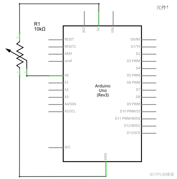
从电位计链接3条线到你的Arduino主板。第一条链接电位计的一个输出针脚和地;第二条链接电位计的另一个输出针脚和5v电压;第三条线链接电位计的中间针脚和0号模拟输入针脚。
通过转动电位计的轴,可以改变电弧两侧的电阻大小,该电弧链接到电位计的中间针脚。这样就可以改变中间针脚的电压。当转到中间针脚和链接到5v电压那侧时,阻值趋向于0,中间针脚的电压趋向于5v。当阻值取反时,中间针脚的电压趋向于0v,或接地。这个电压是你正在作为输入读取的模拟电压。
Arduino 有一个内部电路称为模数转换器,它读取变化中的电压并把它转换为0到1023之间的数字。

4. 原理图
5. 程序
/*
AnalogReadVoltage
reads ana anlog input on pin 0, converts it to voltage, and prints the result to the serial
monitor. Attach the center pin of a potentiometer to pin A0, and the outside pins to ground
and +5v.
*/
void setup()
{
Serial.begin(9600);
}
void loop()
{
// read the input on analog pin A0
int sensorValue = analogRead(A0);
Serial.print(sensorValue, DEC);
Serial.print("\t");
// convert the analog reading (which goes from 0--1023) to a voltage (0--255)
float voltage = (sensorValue/1023.0)*5.0;
// print out the value you read
Serial.println(voltage);
}
6. 实验照片

来自 “ ITPUB博客 ” ,链接:http://blog.itpub.net/263104/viewspace-1253798/,如需转载,请注明出处,否则将追究法律责任。
转载于:http://blog.itpub.net/263104/viewspace-1253798/


 被折叠的 条评论
为什么被折叠?
被折叠的 条评论
为什么被折叠?
 到【灌水乐园】发言


