OSPF+MGRE

在这里插入图片描述
在这里插入图片描述
步骤:
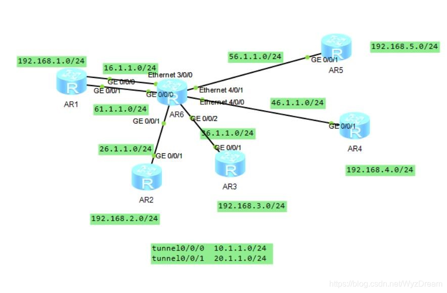
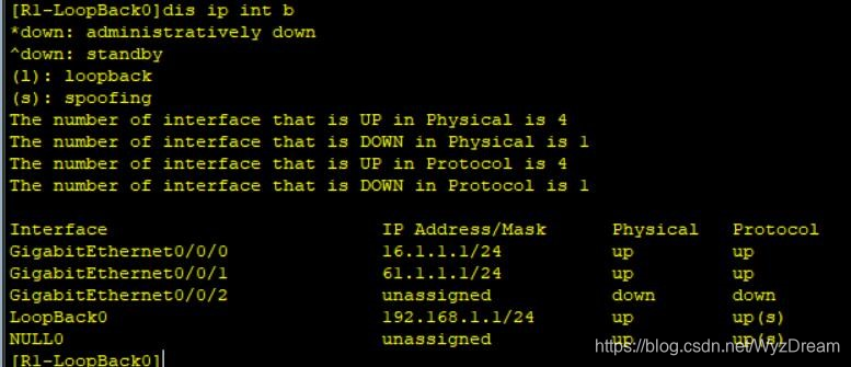
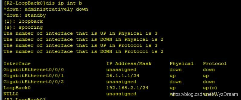
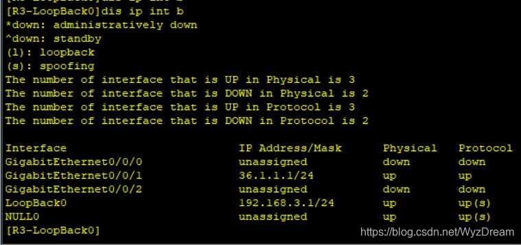
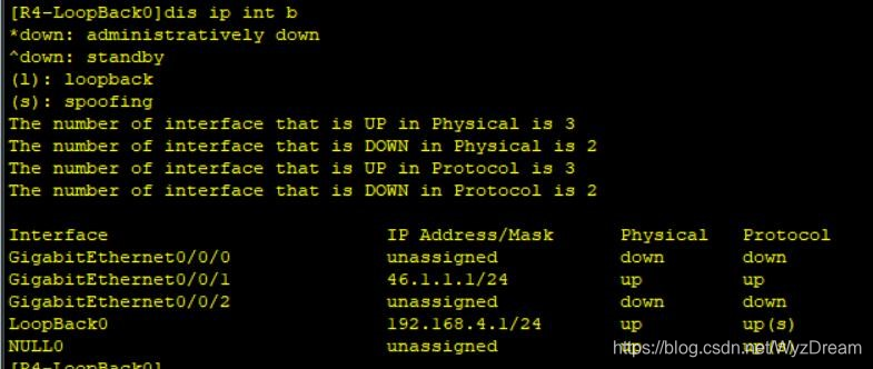
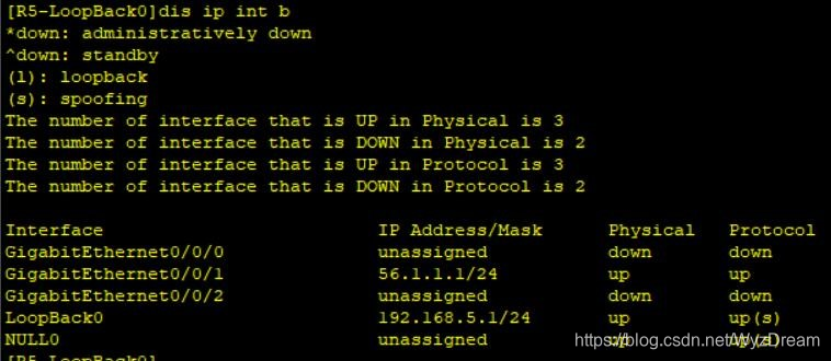
1.根据图中网段,给路由器配置IP地址和环回
在这里插入图片描述
在这里插入图片描述
在这里插入图片描述
在这里插入图片描述
在这里插入图片描述
在这里插入图片描述
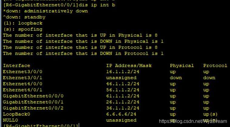
2.将公有网段做通,在边界路由器上写缺省
[R1]ip route-static 0.0.0.0 0 16.1.1.2
[R1]ip route-static 0.0.0.0 0 61.1.1.2
[R2]ip route-static 0.0.0.0 0 26.1.1.1
[R3]ip route-static 0.0.0.0 0 36.1.1.2
[R4]ip route-static 0.0.0.0 0 46.1.1.2
[R5]ip route-static 0.0.0.0 0 56.1.1.2

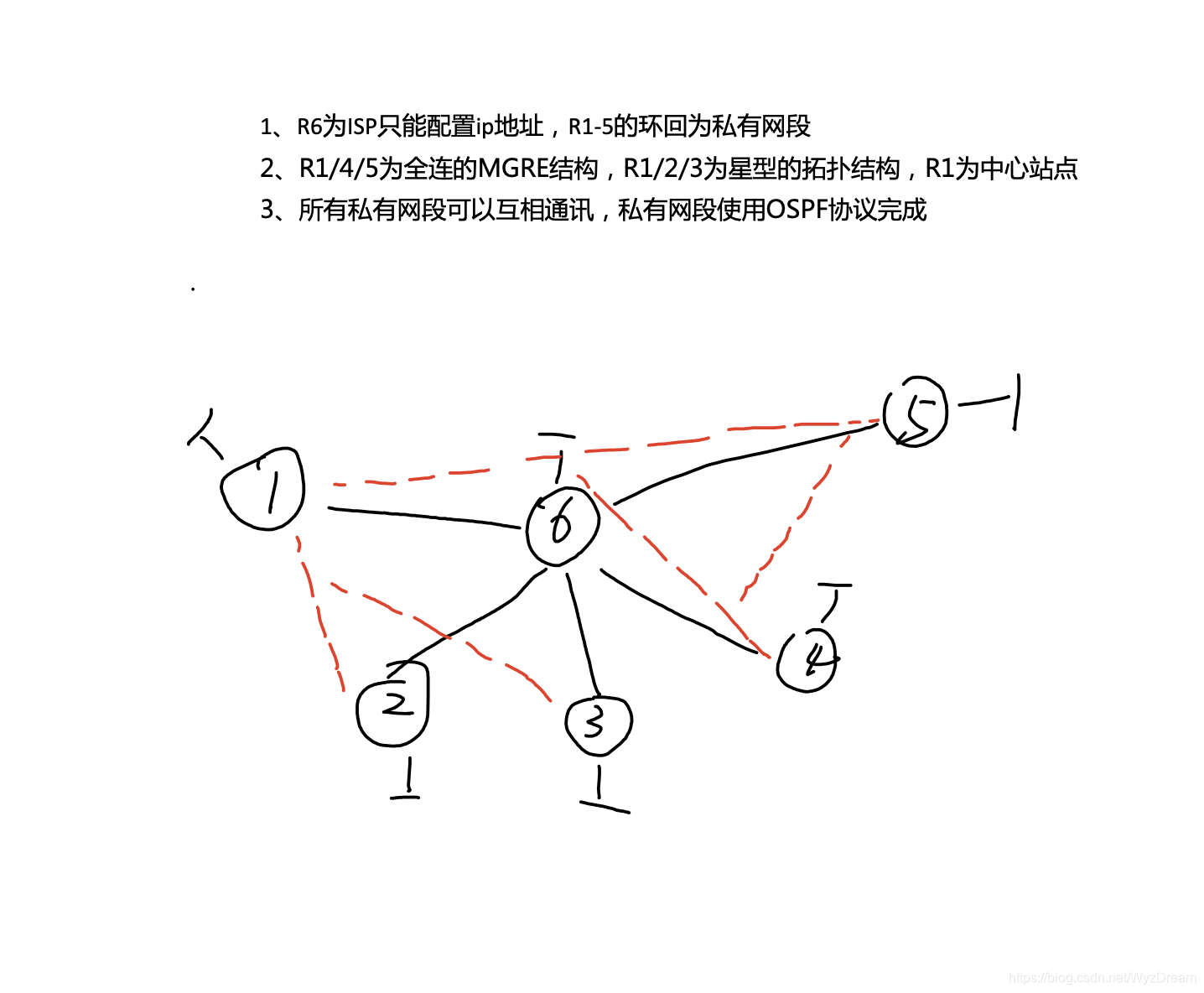
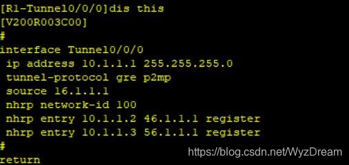
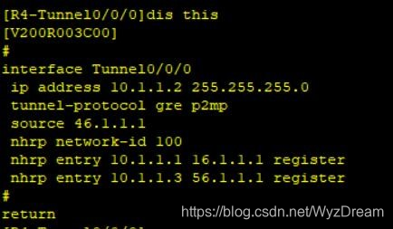
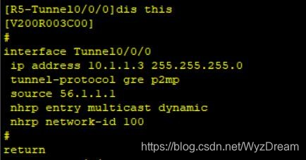
3.R1、R4、R5为全连的MGRE结构
在这里插入图片描述
在这里插入图片描述
在这里插入图片描述
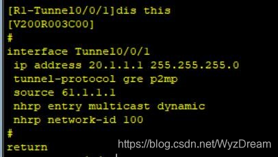
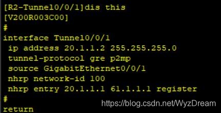
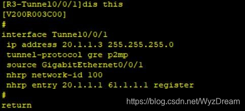
4.R1、R2、R3为星型拓扑结构,R1为中心站点
在这里插入图片描述
在这里插入图片描述
在这里插入图片描述
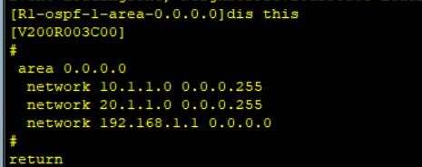
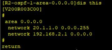
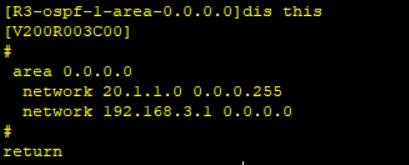
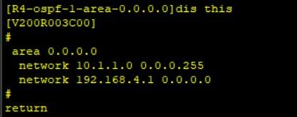
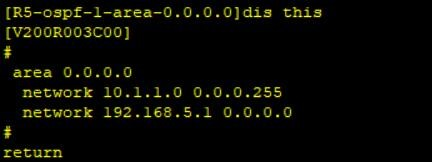
5.做通私网----------启ospf协议
在这里插入图片描述
在这里插入图片描述
在这里插入图片描述
在这里插入图片描述
在这里插入图片描述
6.由于MGRE默认为点到点的工作方式,该方式只能建立一个邻居,故在NBMA环境下将无法和所有节点建立关系,因此需要修改接口的工作方式
[R1]int Tunnel 0/0/0
[R1-Tunnel0/0/0]ospf network-type broadcast
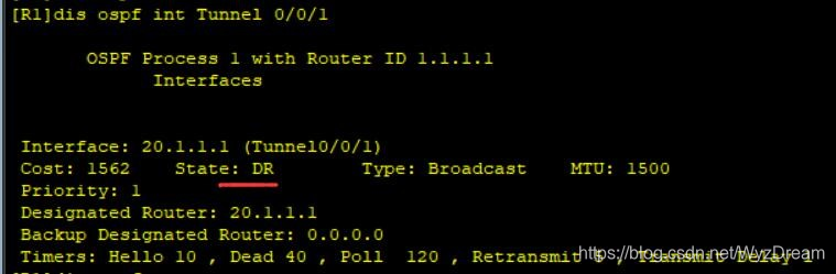
[R1]int Tunnel 0/0/1
[R1-Tunnel0/0/1]ospf network-type broadcast

[R2]int Tunnel 0/0/1
[R2-Tunnel0/0/1]ospf network-type broadcast

[R3]int Tunnel 0/0/1
[R3-Tunnel0/0/1]ospf network-type broadcast

[R4]int Tunnel 0/0/0
[R4-Tunnel0/0/0]ospf network-type broadcast

[R5]int Tunnel 0/0/0
[R5-Tunnel0/0/0]ospf network-type broadcast

7.将R2,R3tunnel口的优先级改为0,使它们不参选
在这里插入图片描述
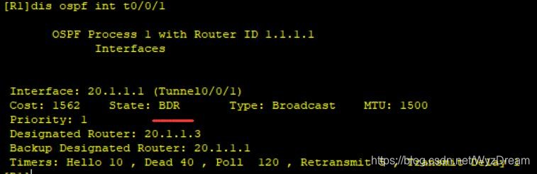
此时R1不是DR,将R2,R3tunnel口的优先级改为0,使它们不参选

[R2]int t0/0/1
[R2-Tunnel0/0/1]ospf d
[R2-Tunnel0/0/1]ospf dr-priority 0

[R3]int t0/0/1
[R3-Tunnel0/0/1]ospf d
[R3-Tunnel0/0/1]ospf dr-priority 0
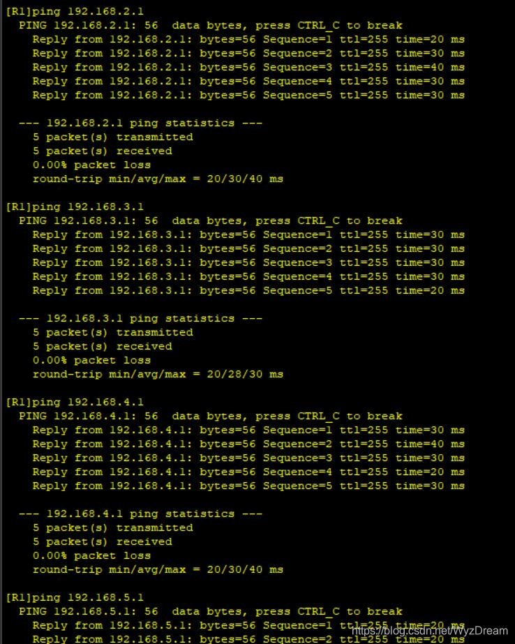
在这里插入图片描述
8.测试
在这里插入图片描述

### OSPF Point-to-Multipoint Configuration with MGRE Tunneling Explanation and Setup Guide #### Understanding the Basics of OSPF Point-to-Multipoint Networks In a point-to-multipoint network type within OSPF, routers do not elect Designated Routers (DRs) or Backup Designated Routers (BDRs). Neighbors are established directly between endpoints. The default Hello interval is set to 30 seconds while the Dead interval stands at 120 seconds[^1]. This configuration simplifies neighbor establishment but requires careful planning when integrating advanced features like Multi-Point GRE tunnels. #### Introduction to Multi-Point GRE Tunnels Multi-Point GRE (mGRE) allows multiple remote sites to connect through a single virtual interface on an endpoint device without requiring individual physical interfaces for each connection. mGRE can significantly reduce complexity in hub-and-spoke topologies by enabling dynamic tunnel creation based on IPsec policies or other criteria. #### Combining OSPF Point-to-Multipoint Network Type with mGRE When combining these two technologies: - **Hub Router**: Configured as both ends of all spokes' mGRE sessions. - **Spoke Routers**: Each configured individually pointing back towards the central hub router's public address over which they will establish their respective mGRE session(s). The combination leverages OSPF’s ability to form adjacencies easily across non-broadcast multi-access networks such as those created via mGRE tunnels. It also benefits from OSPF's inherent support for point-to-multipoint configurations where DR/BDR elections aren't necessary due to direct adjacency formation among participating nodes. #### Example Configuration Steps for Hub Router Using Huawei CLI Syntax Below demonstrates how one might configure this scenario using commands similar to what would be found in a typical enterprise-grade environment provided by vendors like Huawei. ```shell # Enter system view mode system-view # Create loopback interface used for establishing mGRE connections interface LoopBack0 ip address 192.168.1.1 255.255.255.255 # Configure real Ethernet port that connects outside world interface GigabitEthernet0/0/1 ip address dhcp # Define mGRE template tunnel-template gre multipoint name mgre-tpl source-interface LoopBack0 destination any # Apply mGRE settings onto actual tunnel interface interface Tunnel0 undo ip address tunnel-protocol gre multipoint apply tunnel-template mgre-tpl ospf enable area 0 ``` For spoke routers, replace `source-interface` command under `tunnel-template` section accordingly depending upon local addressing scheme; ensure consistency throughout entire deployment regarding naming conventions applied here too. #### Verification Commands After Setup Completion Once completed successfully, verify operation status utilizing following instructions available inside most modern networking gear including models produced by companies mentioned earlier: ```shell display ospf peer brief # Check current state of OSPF peers display ip routing-table # Review learned routes after convergence has occurred ping -a <Source_IP> <Destination_IP> # Test reachability between different segments involved ``` --related questions-- 1. How does changing OSPF hello/dead timers affect stability in large-scale deployments? 2. What considerations should administrators take into account before implementing mGRE solutions? 3. Can you explain more about configuring OSPF route-id specifically for devices running OSPF protocol? 4. In what scenarios could deploying OSPF stub areas improve performance compared against standard ones?
评论
添加红包

请填写红包祝福语或标题

红包个数最小为10个

红包金额最低5元

当前余额3.43前往充值 >
需支付:10.00
成就一亿技术人!
领取后你会自动成为博主和红包主的粉丝 规则
hope_wisdom
发出的红包
实付
使用余额支付
点击重新获取
扫码支付
钱包余额 0

抵扣说明:

1.余额是钱包充值的虚拟货币,按照1:1的比例进行支付金额的抵扣。
2.余额无法直接购买下载,可以购买VIP、付费专栏及课程。

余额充值