


题目要求
1. R6为ISP只能配置IP地址,R1-R5的环回为私有网段
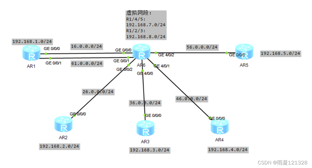
2. R1/4/5为全连的MGRE结构,R1/2/3为星型的拓扑结构,R1为中心站点
3. 所有私有网段可以互相通讯,私有网段使用osPF完成题目分析
1. IP划分,虚拟网段划分
2. R1/4/5为全连结构,每一个节点都为中心节点;R1/2/3为星型结构,R1为中心节点,R2/3为分支节点
3. 启用OSPF,虚拟接口更改接口类型,分支节点修改接口优先级为0
实验配置
IP划分
虚拟网段:
R1/4/5
192.168.7.0/24
R1/2/3
192.168.8.0/24

私网网段:
R1
192.168.1.0/24
R2
192.168.2.0/24
R3
192.168.3.0/24
R4
192.168.4.0/24
R5
192.168.5.0/24

骨干链路网段:
R1,R6
16.0.0.0/24
61.0.0.0/24

R2,R6
26.0.0.0/24

R3,R6
36.0.0.0/24

R4,R6
46.0.0.0/24

R5,R6
56.0.0.0/24
路由器配置内容
在进行R1/4/5的MGRE环境配置时,应先将其隧道接口关闭(进入接口输入 shutdown 命令),否则可能会出现注册不成功
R1配置:
配置IP地址
interface GigabitEthernet0/0/0
 ip address 16.0.0.1 255.255.255.0
interface GigabitEthernet0/0/1
 ip address 61.0.0.1 255.255.255.0

配置环回代表私网地址
interface LoopBack0
 ip address 192.168.1.1 255.255.255.0

创建VPN隧道
interface Tunnel0/0/0
 ip address 192.168.7.1 255.255.255.0
 tunnel-protocol gre p2mp
 source 16.0.0.1
interface Tunnel0/0/1
 ip address 192.168.8.1 255.255.255.0
 tunnel-protocol gre p2mp
 source 61.0.0.1

修改隧道接口类型,Tunnel0/0/0和Tunnel0/0/1口都要修改
 ospf network-type broadcast

开启伪广播,两个Tunnel口都要开启
 nhrp entry multicast dynamic

向中心节点R4,R5注册
 nhrp entry 192.168.7.2 46.0.0.1 register
 nhrp entry 192.168.7.3 56.0.0.1 register


启用OSPF,配置RID,在区域0内宣告私网网段和虚拟网段
ospf 1 router-id 1.1.1.1
 area 0.0.0.0
  network 192.168.1.0 0.0.0.255
  network 192.168.7.0 0.0.0.255
  network 192.168.8.0 0.0.0.255

配置缺省路由
ip route-static 0.0.0.0 0.0.0.0 16.0.0.2
ip route-static 0.0.0.0 0.0.0.0 61.0.0.2


R2配置:
IP地址
interface GigabitEthernet0/0/0
 ip address 26.0.0.1 255.255.255.0

环回
interface LoopBack0
 ip address 192.168.2.1 255.255.255.0

VPN隧道
interface Tunnel0/0/0
 ip address 192.168.8.2 255.255.255.0
 tunnel-protocol gre p2mp
 source 26.0.0.1

修改隧道接口类型
 ospf network-type broadcast

修改隧道接口优先级
 ospf dr-priority 0


向中心节点R1注册
 nhrp entry 192.168.8.1 61.0.0.1 register

启用OSPF,配置RID,在区域0内宣告私网网段和虚拟网段
ospf 1 router-id 2.2.2.2
 area 0.0.0.0
  network 192.168.2.0 0.0.0.255
  network 192.168.8.0 0.0.0.255

配置缺省路由
ip route-static 0.0.0.0 0.0.0.0 26.0.0.2


R3配置:
IP地址
interface GigabitEthernet0/0/0
 ip address 36.0.0.1 255.255.255.0

环回接口
interface LoopBack0
 ip address 192.168.3.1 255.255.255.0

VPN隧道
interface Tunnel0/0/0
 ip address 192.168.8.3 255.255.255.0
 tunnel-protocol gre p2mp
 source 36.0.0.1

修改隧道接口类型
 ospf network-type broadcast

修改隧道接口优先级
 ospf dr-priority 0


向中心节点R1注册
 nhrp entry 192.168.8.1 61.0.0.1 register

启用OSPF,配置RID,在区域0内宣告私网网段和虚拟网段
ospf 1 router-id 3.3.3.3
 area 0.0.0.0
  network 192.168.3.0 0.0.0.255
  network 192.168.8.0 0.0.0.255

配置缺省路由
ip route-static 0.0.0.0 0.0.0.0 36.0.0.2


R4配置:
#
interface GigabitEthernet0/0/0
 ip address 46.0.0.1 255.255.255.0
#
interface LoopBack0
 ip address 192.168.4.1 255.255.255.0
#
interface Tunnel0/0/0
 ip address 192.168.7.2 255.255.255.0
 tunnel-protocol gre p2mp
 source 46.0.0.1
 ospf network-type broadcast
#
向中心节点R1,R5注册
 nhrp entry 192.168.7.3 56.0.0.1 register
 nhrp entry 192.168.7.1 16.0.0.1 register
#
ospf 1 router-id 4.4.4.4
 area 0.0.0.0
  network 192.168.4.0 0.0.0.255
  network 192.168.7.0 0.0.0.255
#
ip route-static 0.0.0.0 0.0.0.0 46.0.0.2


R5配置:
#
interface GigabitEthernet0/0/0
 ip address 56.0.0.1 255.255.255.0
#
interface LoopBack0
 ip address 192.168.5.1 255.255.255.0
#
interface Tunnel0/0/0
 ip address 192.168.7.3 255.255.255.0
 tunnel-protocol gre p2mp
 source 56.0.0.1
 ospf network-type broadcast
 nhrp entry 192.168.7.2 46.0.0.1 register
 nhrp entry 192.168.7.1 16.0.0.1 register
#
ospf 1 router-id 5.5.5.5
 area 0.0.0.0
  network 192.168.5.0 0.0.0.255
  network 192.168.7.0 0.0.0.255
#
ip route-static 0.0.0.0 0.0.0.0 56.0.0.2


R6配置:
只用配置IP地址
interface GigabitEthernet0/0/0
 ip address 16.0.0.2 255.255.255.0
#
interface GigabitEthernet0/0/1
 ip address 61.0.0.2 255.255.255.0
#
interface GigabitEthernet0/0/2
 ip address 26.0.0.2 255.255.255.0
#
interface GigabitEthernet4/0/0
 ip address 36.0.0.2 255.255.255.0
#
interface GigabitEthernet4/0/1
 ip address 46.0.0.2 255.255.255.0
#
interface GigabitEthernet4/0/2
 ip address 56.0.0.2 255.255.255.0
实验结果
R1映射表

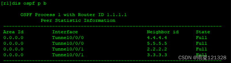
R1邻居表
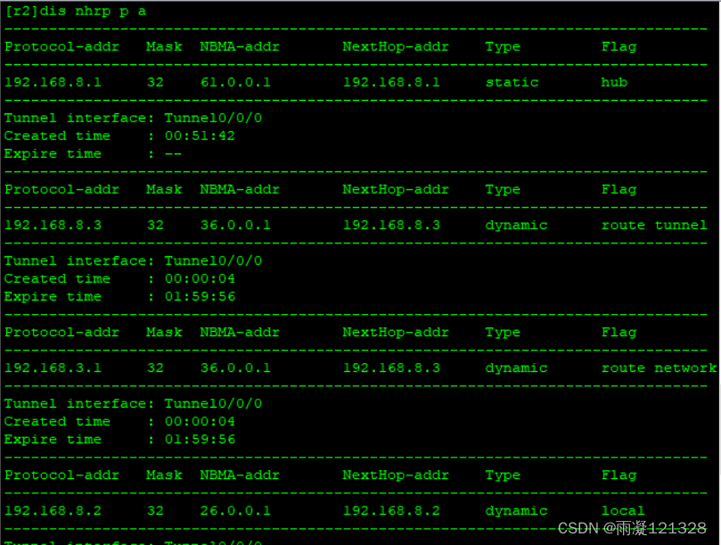
R2映射表
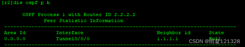
R2邻居表
 R4映射表
R4映射表
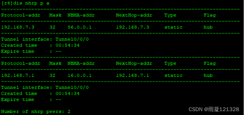
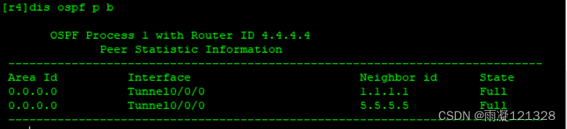
R4邻居表
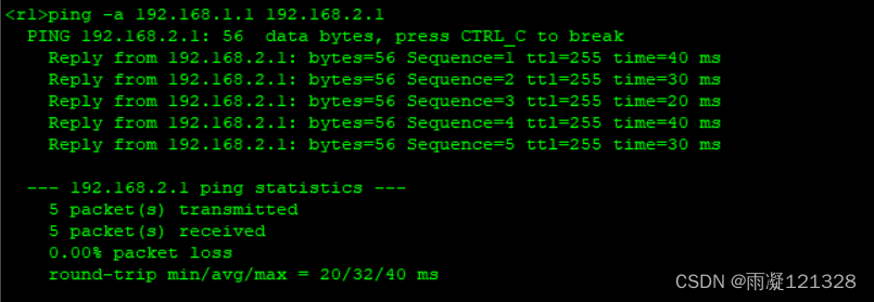
R1 ping R2
R1 ping R4

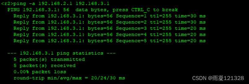
R2 ping R3
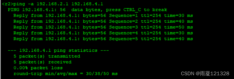
R2 ping R4
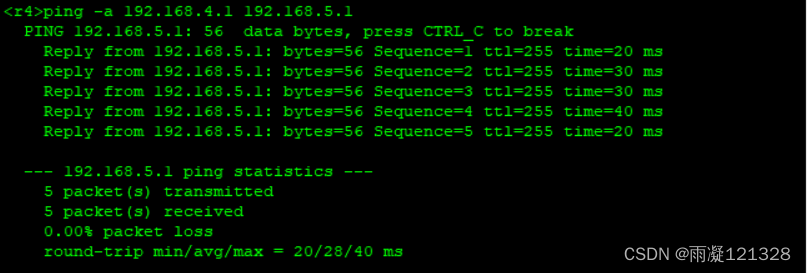
R4 ping R5


 3136
3136

 被折叠的 条评论
为什么被折叠?
被折叠的 条评论
为什么被折叠?
 到【灌水乐园】发言


