


 本文详细描述了一项实验,涉及配置基础网络结构(IP地址和缺省路由),搭建MGRE(多标签GRE隧道)环境,以及使用OSPF实现全网可达,同时调整R1、R5、R6设备的网络类型以统一中心角色和P2MP配置。
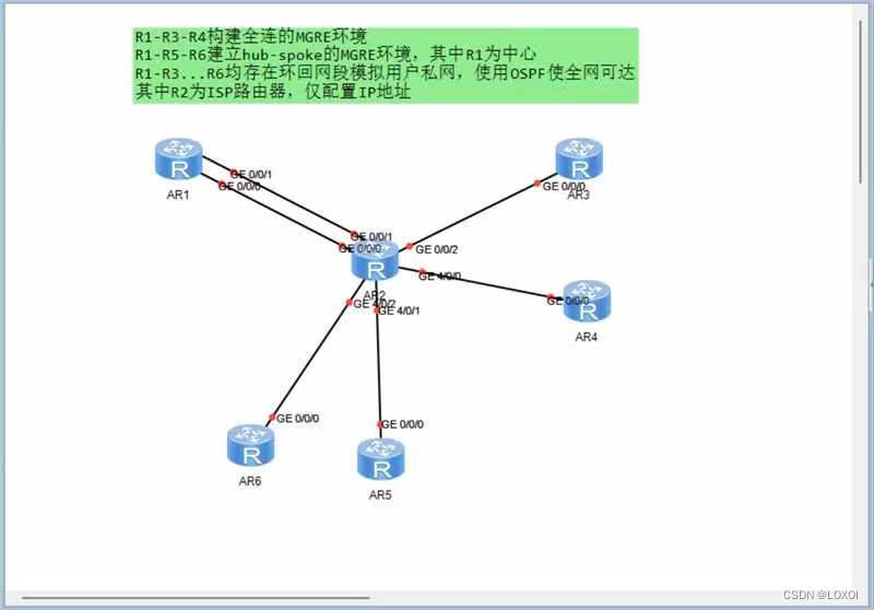
1.实验要求:
2.实验步骤:
2.1完成基础配置:
根据实验要求先完成各基础配置,再进行后续的操作
2.1.1 IP的配置
R1: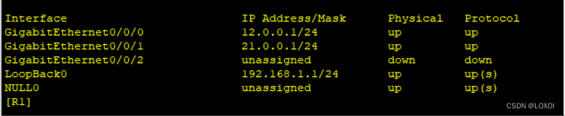
R3: 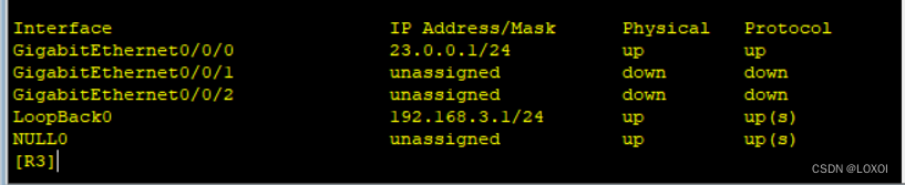
R4: 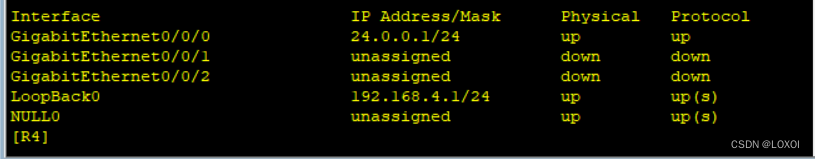
R5: 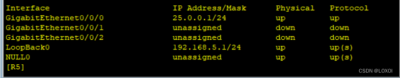
R6 :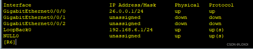
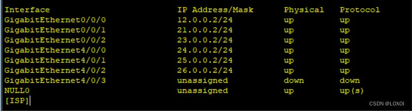
R2 :将R2设置为ISP路由
2.1.2 缺省路由的配置
[R1]ip route-static 0.0.0.0 0 12.0.0.2
[R1]ip route-static 0.0.0.0 0 21.0.0.2[R3]ip route-static 0.0.0.0 0 23.0.0.2
[R4]ip route-static 0.0.0.0 0 24.0.0.2
[R5]ip route-static 0.0.0.0 0 25.0.0.2
[R6]ip route-static 0.0.0.0 0 26.0.0.2
2.2 搭建R1-R3-R4全连的MGRE环境
R1:
[R1]int t0/0/0
[R1-Tunnel0/0/0]ip address 192.168.2.1 24
[R1-Tunnel0/0/0]tunnel-protocol gre p2mp
[R1-Tunnel0/0/0]source 21.0.0.1
[R1-Tunnel0/0/0]nhrp network-id 6
[R1-Tunnel0/0/0]nhrp entry multicast dynamic
[R1-Tunnel0/0/0]nhrp entry 192.168.2.3 23.0.0.1 register
[R1-Tunnel0/0/0]nhrp entry 192.168.2.3 24.0.0.1 register
R3:
[R3]int t 0/0/0
[R3-Tunnel0/0/0]ip address 192.168.2.3 24
[R3-Tunnel0/0/0]tunnel-protocol gre p2mp
[R3-Tunnel0/0/0]source 23.0.0.1
[R3-Tunnel0/0/0]nhrp entry multicast dynamic
[R3-Tunnel0/0/0]nhrp network-id 6
[R3-Tunnel0/0/0]nhrp entry 192.168.2.1 21.0.0.1 register
[R3-Tunnel0/0/0]nhrp entry 192.168.4.1 24.0.0.1 register
R4:
[R4]int t 0/0/0
[R4-Tunnel0/0/0]ip address 192.168.2.4 24
[R4-Tunnel0/0/0]tunnel-protocol gre p2mp
[R4-Tunnel0/0/0]source 24.0.0.1
[R4-Tunnel0/0/0]nhrp network-id 6
[R4-Tunnel0/0/0]nhrp entry multicast dynamic
[R4-Tunnel0/0/0]nhrp entry 192.168.2.1 21.0.0.1 register
[R4-Tunnel0/0/0]nhrp entry 192.168.2.3 23.0.0.1 register
2.3 建立R1-R5-R6hub-spoke的MGRE环境,其中R1为中心
R1:
[R1]int t 0/0/1
[R1-Tunnel0/0/1]ip address 192.168.7.1 24
[R1-Tunnel0/0/1]tunnel-protocol gre p2mp
[R1-Tunnel0/0/1]source 12.0.0.1
[R1-Tunnel0/0/1]nhrp network-id 6
[R1-Tunnel0/0/1]nhrp entry multicast dynamic
R5:
[R5]int t 0/0/0
[R5-Tunnel0/0/0]ip address 192.168.7.5 24
[R5-Tunnel0/0/0]tunnel-protocol gre p2mp
[R5-Tunnel0/0/0]source 25.0.0.1
[R5-Tunnel0/0/0]nhrp network-id 6
[R5-Tunnel0/0/0]nhrp entry 192.168.7.1 12.0.0.1 register
R6:
[R6]int t 0/0/0
[R6-Tunnel0/0/0]ip address 192.168.7.6 24
[R6-Tunnel0/0/0]tunnel-protocol gre p2mp
[R6-Tunnel0/0/0]source 26.0.0.1
[R6-Tunnel0/0/0]nhrp network-id 6
[R6-Tunnel0/0/0]nhrp entry 192.168.7.1 12.0.0.1 register
2.4 R1-R3...R6均存在环回网段模拟用户私网,使用OSPF使全网可达
[R1]ospf 1 router-id 1.1.1.1
[R1-ospf-1]area 0
[R1-ospf-1-area-0.0.0.0]network 192.168.1.0 0.0.0.255
[R1-ospf-1-area-0.0.0.0]network 192.168.2.0 0.0.0.255
[R1-ospf-1-area-0.0.0.0]network 192.168.7.0 0.0.0.255
[R3]ospf 1 router-id 3.3.3.3
[R3-ospf-1]area 0
[R3-ospf-1-area-0.0.0.0]network 192.168.3.0 0.0.0.255
[R3-ospf-1-area-0.0.0.0]network 192.168.2.0 0.0.0.255
[R4]ospf 1 router-id 4.4.4.4
[R4-ospf-1]area 0
[R4-ospf-1-area-0.0.0.0]network 192.168.4.0 0.0.0.255
[R4-ospf-1-area-0.0.0.0]network 192.168.2.0 0.0.0.255
[R5]ospf 1 router-id 5.5.5.5
[R5-ospf-1]area 0
[R5-ospf-1-area-0.0.0.0]network 192.168.5.0 0.0.0.255
[R5-ospf-1-area-0.0.0.0]network 192.168.7.0 0.0.0.255
[R6]ospf 1 router-id 6.6.6.6
[R6-ospf-1]area 0
[R6-ospf-1-area-0.0.0.0]network 192.168.6.0 0.0.0.255
[R6-ospf-1-area-0.0.0.0]network 192.168.7.0 0.0.0.255
2.5 在R1R3R4上让mgre环境中心角色认知统一,在R1R5R6上修改类型为p2mp
[R1]int t0/0/0
[R1-Tunnel0/0/0]ospf network-type broadcast
[R1]int t0/0/1
[R1-Tunnel0/0/1]ospf network-type p2mp
[R5]int t0/0/0
[R5-Tunnel0/0/0]ospf network-type p2mp
[R6]int t0/0/0
[R6-Tunnel0/0/0]ospf network-type p2mp


 被折叠的 条评论
为什么被折叠?
被折叠的 条评论
为什么被折叠?
 到【灌水乐园】发言


