


 本文介绍了Verilog的基础概念,包括基本门电路的设计如与门、或门、非门等,向量与总线的使用方法,以及如何实现复杂的组合逻辑电路。文章还详细解释了连续赋值与程序块赋值的区别,并提供了多个实例来帮助理解。
这里写目录标题
源:https://hdlbits.01xz.net/wiki/Wire4
wire
assign left_side = right_side // "continuous assignment" 有向
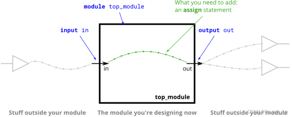
除了"continuous assignment",Verilog还有三种其他赋值类型用于程序块(procedural blocks),其中两种是可综合的。在开始使用程序块之前,我们不会使用它们。
wire4
当您有多个赋值语句时,它们在代码中出现的顺序并不重要。与编程语言不同,赋值语句(“连续赋值”)描述事物之间的连接,而不是将值从一个事物复制到另一个事物的动作。
inverter (NOT-gate)
Verilog有不同的按位NOT(~)和逻辑NOT(!)运算符,如同C。因为我们在这里只使用一位,所以选择哪一位并不重要。
assign out = ~in;
And gate
"assign"声明将把逻辑电平驱动到导线上。一条导线不能有多个驱动(如果有,它的逻辑电平是多少?)
Verilog has separate bitwise-AND (&) and logical-AND (&&) operators, like C. Since we’re working with a one-bit here, it doesn’t matter which we choose.
assign out = a && b;
Nor gate
assign out = ~(a|b);
Xnor gate(同或)
assign out = (a & b)|(~a & ~b);
// 或
assign out = ~a^b;		// ^为异或
// 或 assign out = (~a)^b;
wire的定义
请注意,导线仅由一个源(门的输出)驱动,但可以提供多个输入。
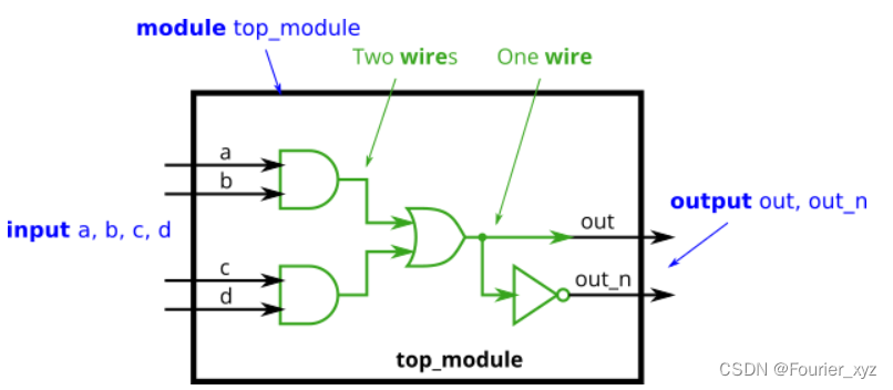
module top_module(input a,input b,input c,input d,output out,output out_n);

    wire or_in_1;
    wire or_in_2;

    assign or_in_1 = a&b;
    assign or_in_2 = c&d;
    assign out = or_in_1|or_in_2;
    assign out_n = ~out;

endmodule
7458
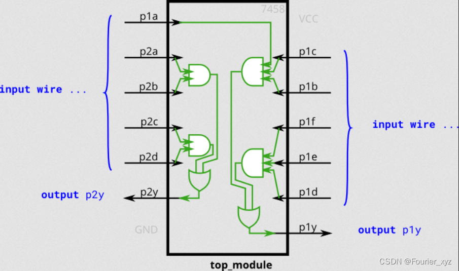
module top_module (input p1a, p1b, p1c, p1d, p1e, p1f,output p1y,input p2a, p2b, p2c, p2d,output p2y);
    wire p1_1;
    wire p1_2;
    assign p1_1 = p1a&p1b&p1c;
    assign p1_2 = p1d&p1e&p1f;
    assign p1y  = p1_1|p1_2;

    wire p2_1;
    wire p2_2;
    assign p2_1 = p2c&p2d;
    assign p2_2 = p2a&p2b;
    assign p2y  = p2_1|p2_2;


endmodule
Vector(向量,bus,总线)
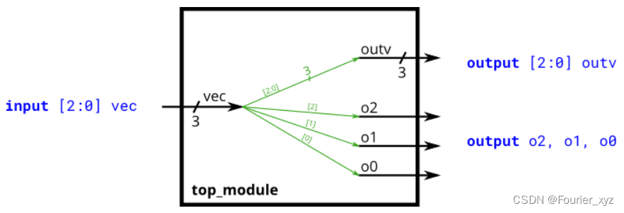
module top_module (input wire [2:0] vec,output wire [2:0] outv,output wire o2,output wire o1,output wire o0); // Module body starts after module declaration
    assign o0 = vec[0];
    assign o1 = vec[1];
    assign o2 = vec[2];
    assign outv = vec;

endmodule
wire [7:0] w;         // 8-bit wire
reg  [4:1] x;         // 4-bit reg
output reg [0:0] y;   // 1-bit reg that is also an output port (this is still a vector)
input wire [3:-2] z;  // 6-bit wire input (negative ranges are allowed)
output [3:0] a;       // 4-bit output wire. Type is 'wire' unless specified otherwise.
wire [0:7] b;         // 8-bit wire where b[0] is the most-significant bit. (最高有效位)
/// 注意最低有效位和下标的对应关系
隐式网(Implicit nets):
隐式网易导致bug,若变量未声明,但被定义(assign),其就会被隐式声明为1 bit wire类型(其实你打算将其声明为向量的)。通过添加 `default_nettype none 宏定义会关闭隐式声明功能,那么这样一来,使用未声明的变量就会变成一个 Error 而不再只是 Warning。
wire [2:0] a, c;    // Two vectors
assign a = 3'b101;  // a = 101
assign b = a;       // b =   1  implicitly-created wire	(发生了隐式类型定义)
assign c = b;       // c = 001  <-- bug
my_module i1 (d,e); // d and e are implicitly one-bit wide if not declared.
                    // This could be a bug if the port was intended to be a vector.
Unpacked vs. Packed Arrays
由向量作为元素的数组,数组长度在变量名后。
reg [7:0] mem [255:0];   // 256 unpacked elements, each of which is a 8-bit packed vector of reg.
reg mem2 [28:0];         // 29 unpacked elements, each of which is a 1-bit reg.
向量的部分选择
在 assign 赋值操作中,如果等号左右两侧信号的位宽不同,那么就会进行截断或者补零操作。
w[3:0]      // Only the lower 4 bits of w
x[1]        // The lowest bit of x
x[1:1]      // ...also the lowest bit of x
z[-1:-2]    // Two lowest bits of z
b[3:0]      // Illegal. Vector part-select must match the direction of the declaration.(如果 b 在声明时 声明为 wire [0:3])
b[0:3]      // The *upper* 4 bits of b.
assign w[3:0] = b[0:3];    // Assign upper 4 bits of b to lower 4 bits of w. w[3]=b[0], w[2]=b[1], etc.
/// 这里有个问题,如果两个“向量方向”相同的向量,想要其中的某段赋值到另外一个向量,那咋办?
`default_nettype none     // Disable implicit nets. Reduces some types of bugs.
module top_module(
    input wire [15:0] in,
    output wire [7:0] out_hi,
    output wire [7:0] out_lo );

    assign out_hi = in[15:8];
    assign out_lo = in[7:0];
endmodule
4 bytes颠倒
module top_module(input [31:0] in,output [31:0] out );//
    assign out[31:24] = in[7:0];
    assign out[23:16] = in[15:8];
    assign out[15:8]  = in[23:16];
    assign out[7:0]   = in[31:24];

endmodule
向量门
前面提到了按位运算和逻辑运算。使用向量时,两种运算符类型之间的区别变得很重要。两个N位向量之间的按位运算复制矢量的每个位的运算,并生成N位输出,而逻辑运算将整个向量视为布尔值(true=非零,false=零),并生成1位输出。

module top_module(input [2:0] a,input [2:0] b,output [2:0] out_or_bitwise,output out_or_logical,output [5:0] out_not);
	assign out_or_bitwise = a|b;
    assign out_or_logical = a||b;
    assign out_not[5:3] = ~b;
    assign out_not[2:0] = ~a;
endmodule
四输入门练习
构建一个4输入组合逻辑电路:in[3:0],
其有3个输出:
· out_and: output of a 4-input AND gate.
· out_or: output of a 4-input OR gate.
· out_xor: output of a 4-input XOR gate.
module top_module(input [3:0] in,output out_and,output out_or,output out_xor);
    assign out_and = ~((~in)&&1);
    assign out_or  = in&&1;
    assign out_xor = in[3]^in[2]^in[1]^in[0];

endmodule

/// 或使用缩减运算符:
module top_module(input [3:0] in,output out_and,output out_or,output out_xor);
    assign out_and = & in;
    assign out_or  = | in;
    assign out_xor = ^ in;
endmodule
连接操作符
{3'b111, 3'b000} => 6'b111000
{1'b1, 1'b0, 3'b101} => 5'b10101
{4'ha, 4'd10} => 8'b10101010     // 4'ha and 4'd10 are both 4'b1010 in binary
连接需要知道每个元素的位宽。连接符可以作为左值或右值。
input [15:0] in;
output [23:0] out;
assign {out[7:0], out[15:8]} = in;      // Swap two bytes. Right side and left side are both 16-bit vectors.
assign out[15:0] = {in[7:0], in[15:8]}; // This is the same thing.
assign out = {in[7:0], in[15:8]};       // This is different. The 16-bit vector on the right is extended to
                                        // match the 24-bit vector on the left, so out[23:16] are zero.
                                        // In the first two examples, out[23:16] are not assigned.
练习:

module top_module (input [4:0] a, b, c, d, e, f,output [7:0] w, x, y, z );//// assign { ... } = { ... };
    // in 5-bit, out 8-bit
    assign w = {a,b[4:2]};
    assign x = {b[1:0],c,d[4]};
    assign y = {d[3:0],e[4:1]};
    assign z = {e[0],f,2'd3};
endmodule
向量倒序
module top_module(input [7:0] in,output [7:0] out);
    assign out = {in[0],in[1],in[2],in[3],in[4],in[5],in[6],in[7]};
endmodule
或
module top_module(input [7:0] in,output [7:0] out);
    always @(*) begin
		for (int i=0; i<8; i++)	// int is a SystemVerilog type. Use integer for pure Verilog.
			out[i] = in[8-i-1];
	end

endmodule
或
module top_module(input [7:0] in,output [7:0] out);
    generate
		genvar i;
		for (i=0; i<8; i = i+1) begin: my_block_name
			assign out[i] = in[8-i-1];
		end
	endgenerate

endmodule
其中的讲究看原文吧:
/*
	// I know you're dying to know how to use a loop to do this:

	// Create a combinational always block. This creates combinational logic that computes the same result
	// as sequential code. for-loops describe circuit *behaviour*, not *structure*, so they can only be used
	// inside procedural blocks (e.g., always block).
	// The circuit created (wires and gates) does NOT do any iteration: It only produces the same result
	// AS IF the iteration occurred. In reality, a logic synthesizer will do the iteration at compile time to
	// figure out what circuit to produce. (In contrast, a Verilog simulator will execute the loop sequentially
	// during simulation.)
	always @(*) begin
		for (int i=0; i<8; i++)	// int is a SystemVerilog type. Use integer for pure Verilog.
			out[i] = in[8-i-1];
	end


	// It is also possible to do this with a generate-for loop. Generate loops look like procedural for loops,
	// but are quite different in concept, and not easy to understand. Generate loops are used to make instantiations
	// of "things" (Unlike procedural loops, it doesn't describe actions). These "things" are assign statements,
	// module instantiations, net/variable declarations, and procedural blocks (things you can create when NOT inside
	// a procedure). Generate loops (and genvars) are evaluated entirely at compile time. You can think of generate
	// blocks as a form of preprocessing to generate more code, which is then run though the logic synthesizer.
	// In the example below, the generate-for loop first creates 8 assign statements at compile time, which is then
	// synthesized.
	// Note that because of its intended usage (generating code at compile time), there are some restrictions
	// on how you use them. Examples: 1. Quartus requires a generate-for loop to have a named begin-end block
	// attached (in this example, named "my_block_name"). 2. Inside the loop body, genvars are read only.
	generate
		genvar i;
		for (i=0; i<8; i = i+1) begin: my_block_name
			assign out[i] = in[8-i-1];
		end
	endgenerate
	*/
也可以参考知乎:https://zhuanlan.zhihu.com/p/58315855


 858
858

 被折叠的 条评论
为什么被折叠?
被折叠的 条评论
为什么被折叠?
 到【灌水乐园】发言


