


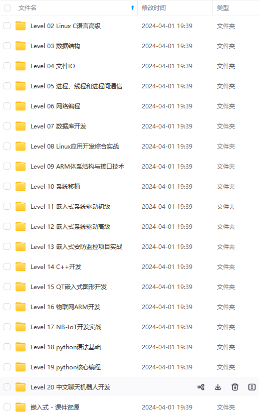
既有适合小白学习的零基础资料,也有适合3年以上经验的小伙伴深入学习提升的进阶课程,涵盖了95%以上物联网嵌入式知识点,真正体系化!
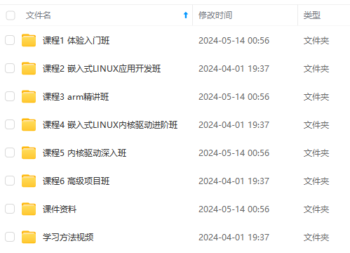
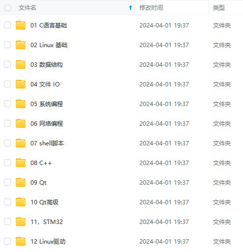
由于文件比较多,这里只是将部分目录截图出来,全套包含大厂面经、学习笔记、源码讲义、实战项目、大纲路线、电子书籍、讲解视频,并且后续会持续更新
需要这些体系化资料的朋友,可以加我V获取:vip1024c (备注嵌入式)
 //绑定输入端口
err_code = nrf\_drv\_gpiote\_in\_init(PIN_IN, &in_config, NULL);
APP\_ERROR\_CHECK(err_code);
 //配置输入事件使能
nrf\_drv\_gpiote\_in\_event\_enable(PIN_IN, true);
}
void ppi_init(void)
{
ret_code_t err_code;
//初始化PPI的模块
err_code = nrf_drv_ppi_init();
APP_ERROR_CHECK(err_code);
/*
nrfx_err_t nrfx_ppi_channel_alloc(nrf_ppi_channel_t * p_channel)
{
nrfx_err_t err_code = NRFX_SUCCESS;
nrf_ppi_channel_t channel;
uint32_t mask = 0;
err_code = NRFX_ERROR_NO_MEM;
mask = NRFX_PPI_PROG_APP_CHANNELS_MASK;
for (channel = NRF_PPI_CHANNEL0;
mask != 0;
mask &= ~nrfx_ppi_channel_to_mask(channel), channel++)//自动从通道0开始寻找通道,找到没使用的
{
NRFX_CRITICAL_SECTION_ENTER();
if ((mask & nrfx_ppi_channel_to_mask(channel)) && (!is_allocated_channel(channel)))
{
channel_allocated_set(channel);
*p_channel = channel;
err_code = NRFX_SUCCESS;
}
NRFX_CRITICAL_SECTION_EXIT();
if (err_code == NRFX_SUCCESS)
{
NRFX_LOG_INFO(“Allocated channel: %d.”, channel);
break;
}
}
NRFX_LOG_INFO(“Function: %s, error code: %s.”, __func__, NRFX_LOG_ERROR_STRING_GET(err_code));
return err_code;
}
*/
err_code = nrfx_ppi_channel_alloc(&my_ppi_channel);
APP_ERROR_CHECK(err_code);
//设置PPI通道my_ppi_channel的EEP和TEP 两端对应的硬件
//nrfx_err_t nrfx_ppi_channel_assign(nrf_ppi_channel_t channel, uint32_t eep, uint32_t tep)
err_code = nrfx_ppi_channel_assign(my_ppi_channel,
nrfx_gpiote_in_event_addr_get(PIN_IN),
nrfx_gpiote_out_task_addr_get(PIN_OUT));
APP_ERROR_CHECK(err_code);
//使能PPI通道
err_code = nrfx_ppi_channel_enable(my_ppi_channel);
APP_ERROR_CHECK(err_code);
}
**PPI group 的使用**
通过 CHG[n] 寄存器配置组绑定的通道:
//把通道0和通道1 绑定到PPI group0之上
NRF\_PPI->CHG[0]=0x03;

PPI group使用示例(寄存器版本):
示例1:
…//gpiote_init
void ppi_init(void)
{
// 配置PPI通道0,一端接GPIOTE事件0,一端接GPIOTE任务1
NRF_PPI->CH[0].EEP = (uint32_t)(&NRF_GPIOTE->EVENTS_IN[0]);
NRF_PPI->CH[0].TEP = (uint32_t)(&NRF_GPIOTE->TASKS_OUT[1]);
// 配置PPI通道1,一端接GPIOTE事件2,一端接GPIOTE任务3
NRF_PPI->CH[1].EEP = (uint32_t)(&NRF_GPIOTE->EVENTS_IN[2]);
NRF_PPI->CH[1].TEP = (uint32_t)(&NRF_GPIOTE->TASKS_OUT[3]);
//把通道0和通道1 绑定到PPI group0之上
NRF_PPI->CHG[0]=0x03;
}
/*通过按钮来管理组的开启与关闭*/
int main(void)
{
gpiote_init();
ppi_init();
KEY_Init();
LED_Init();
LED3_Close();
LED4_Close();
while (true)
{
if( KEY3_Down()== 0){
LED4_Close();
NRF_PPI->TASKS_CHG[0].EN = 1;//使能PPI group0
LED3_Toggle();
}
if( KEY4_Down()== 0){
LED3_Close();
NRF_PPI->TASKS_CHG[0].DIS = 1;//关闭PPI group0
LED4_Toggle();
}
}
}
示例2:
…//gpiote_init
void ppi_init(void)
{
// 配置PPI通道0,一端接GPIOTE事件0,一端接GPIOTE任务1
NRF_PPI->CH[0].EEP = (uint32\_t)(&NRF_GPIOTE->EVENTS_IN[0]);
NRF_PPI->CH[0].TEP = (uint32\_t)(&NRF_GPIOTE->TASKS_OUT[1]);
// 配置PPI通道1,一端接GPIOTE事件2,一端接GPIOTE任务3
NRF_PPI->CH[1].EEP = (uint32\_t)(&NRF_GPIOTE->EVENTS_IN[2]);
NRF_PPI->CH[1].TEP = (uint32\_t)(&NRF_GPIOTE->TASKS_OUT[3]);
//把通道0和通道1 绑定到PPI group0之上
NRF_PPI->CHG[0]=0x03;
//通过KEY3的事件触发使能PPI组的任务
NRF_PPI->CH[2].EEP = (uint32\_t)(&NRF_GPIOTE->EVENTS_IN[4]);
NRF_PPI->CH[2].TEP = (uint32\_t)(&NRF_PPI->TASKS_CHG[0].EN);
NRF_PPI->CHEN = (PPI_CHEN_CH2_Enabled << PPI_CHEN_CH2_Pos);
/\*
有一个疑问,为什么使能PPI组可以使用PPI,但是我下面的这段代码
用PPI禁止PPI组就没有效果,目前是不太明白的
*/
// NRF_PPI->CH[3].EEP = (uint32_t)(&NRF_GPIOTE->EVENTS_IN[5]);
// NRF_PPI->CH[3].TEP = (uint32_t)(&NRF_PPI->TASKS_CHG[0].DIS);
// NRF_PPI->CHEN = (PPI_CHEN_CH3_Enabled << PPI_CHEN_CH3_Pos);
}
…
while (1){
}
上面的ex2有一个问题,就是使能PPI组可以通过KEY3的事件自动触发,但是加上KEY4的事件想禁止PPI组的时候,实际上就有问题了,没有反应,KEY3也没用了,不知道是哪里出了问题


PPI group使用示例(库函数版本):
nrf_ppi_channel_t my_ppi_channel1;
nrf_ppi_channel_t my_ppi_channel2;
nrf_ppi_channel_group_t qf_ppi_group;
…
void ppi_init(void)
{
ret_code_t err_code;
//初始化PPI的模块
err_code = nrf_drv_ppi_init();
APP_ERROR_CHECK(err_code);
//配置PPI的频道
err_code = nrfx_ppi_channel_alloc(&my_ppi_channel1);
APP_ERROR_CHECK(err_code);
//设置PPI通道my_ppi_channel的EEP和TEP 两端对应 输出任务1和输入事件3
err_code = nrfx_ppi_channel_assign(my_ppi_channel1,
nrfx_gpiote_in_event_addr_get(BSP_BUTTON_0),
nrfx_gpiote_out_task_addr_get(LED_1));
APP_ERROR_CHECK(err_code);
//配置PPI的频道
err_code = nrfx_ppi_channel_alloc(&my_ppi_channel2);
APP_ERROR_CHECK(err_code);
//设置PPI通道my_ppi_channel的EEP和TEP 两端对应 输出任务2和输入事件4
err_code = nrfx_ppi_channel_assign(my_ppi_channel2,
nrfx_gpiote_in_event_addr_get(BSP_BUTTON_1),
nrfx_gpiote_out_task_addr_get(LED_2));
APP_ERROR_CHECK(err_code);
//申请PPI组,分配的组号保存到my\_ppi\_group
err_code = nrfx_ppi_group_alloc(&qf_ppi_group);
APP_ERROR_CHECK(err_code);
//PPI通道my_ppi_channel加入到PPI组my_ppi_group
err_code = nrfx_ppi_channel_include_in_group(my_ppi_channel1,qf_ppi_group);
APP_ERROR_CHECK(err_code);
//PPI通道my_ppi_channel2加入到PPI组my_ppi_group
err_code = nrfx_ppi_channel_include_in_group(my_ppi_channel2,qf_ppi_group);
APP_ERROR_CHECK(err_code);
}
int main(void)
{
ret_code_t err_code;
gpiote_init();
ppi_init();
qf_led_key_init();
while (true)
{
if(nrf_gpio_pin_read(BUTTON_3) == 0)
{
nrf_gpio_pin_clear(LED_3);
nrf_gpio_pin_set(LED_4);
while(nrf_gpio_pin_read(BUTTON_3) == 0){}//等待按键释放
//使能PPI组my_ppi_group
err_code = nrfx_ppi_group_enable(qf_ppi_group);
APP_ERROR_CHECK(err_code);
}
if(nrf_gpio_pin_read(BUTTON_4) == 0)
{
//D4点亮,D3熄灭,指示:PPI组禁止
nrf_gpio_pin_clear(LED_4);
nrf_gpio_pin_set(LED_3);
while(nrf_gpio_pin_read(BUTTON_4) == 0){}//等待按键释放
//禁止PPI组my_ppi_group
err_code = nrfx_ppi_group_disable(qf_ppi_group);
APP_ERROR_CHECK(err_code);
}
}
}
**PPI fork 的使用**
PPI fork使用示例(寄存器版本):
…//gpiote_init
收集整理了一份《2024年最新物联网嵌入式全套学习资料》,初衷也很简单,就是希望能够帮助到想自学提升的朋友。
需要这些体系化资料的朋友,可以加我V获取:vip1024c (备注嵌入式)
一个人可以走的很快,但一群人才能走的更远!不论你是正从事IT行业的老鸟或是对IT行业感兴趣的新人
都欢迎加入我们的的圈子(技术交流、学习资源、职场吐槽、大厂内推、面试辅导),让我们一起学习成长!
8)]
[外链图片转存中…(img-KL01UOji-1715892107458)]
需要这些体系化资料的朋友,可以加我V获取:vip1024c (备注嵌入式)
一个人可以走的很快,但一群人才能走的更远!不论你是正从事IT行业的老鸟或是对IT行业感兴趣的新人
都欢迎加入我们的的圈子(技术交流、学习资源、职场吐槽、大厂内推、面试辅导),让我们一起学习成长!


 被折叠的 条评论
为什么被折叠?
被折叠的 条评论
为什么被折叠?
 到【灌水乐园】发言


