


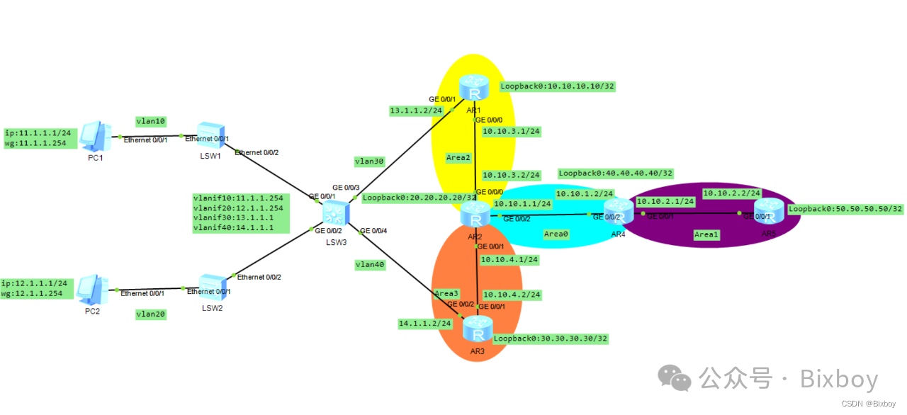
 文章详细描述了在五个交换机(SW1-SW5)上创建VLAN(10,20,30,40),配置接口类型(access/trunk),并为VLAN接口分配IP地址。同时,还涉及AR路由器上的OSPF配置,包括宣告网络和静态路由。
SW1
sysname SW1
#
vlan batch 10 20#创建vlan10和20
#
interface Ethernet0/0/1
port link-type access#端口类型更改为access端口
port default vlan 10#端口归属到vlan10
#
interface Ethernet0/0/2
port link-type trunk#端口类型更改为trunk端口
port trunk allow-pass vlan 10 20#允许vlan10和20通过
SW2
sysname SW2
#
vlan batch 10 20#创建vlan10和20
#
interface Ethernet0/0/1
port link-type access#端口类型更改为access端口
port default vlan 20#端口归属到vlan20
#
interface Ethernet0/0/2
port link-type trunk#端口类型更改为trunk端口
port trunk allow-pass vlan 10 20#允许vlan10和20通过
SW3
sysname SW3
#
vlan batch 10 20 30 40#创建vlan10,20,30,40
#
interface Vlanif10
ip address 11.1.1.254 255.255.255.0
#
interface Vlanif20
ip address 12.1.1.254 255.255.255.0
#
interface Vlanif30
ip address 13.1.1.1 255.255.255.0
#
interface Vlanif40
ip address 14.1.1.1 255.255.255.0
#
interface GigabitEthernet0/0/1
port link-type trunk#端口类型更改为trunk端口
port trunk allow-pass vlan 10 20#允许vlan10和20通过
#
interface GigabitEthernet0/0/2
port link-type trunk#端口类型更改为trunk端口
port trunk allow-pass vlan 10 20#允许vlan10和20通过
#
interface GigabitEthernet0/0/3
port link-type access#端口类型更改为access端口
port default vlan 30#端口归属到vlan40
#
interface GigabitEthernet0/0/4
port link-type access#端口类型更改为access端口
port default vlan 40#端口归属到vlan40
#
ip route-static 0.0.0.0 0.0.0.0 13.1.1.2
ip route-static 0.0.0.0 0.0.0.0 14.1.1.2
AR1
sysname AR1
#
interface GigabitEthernet0/0/0
ip address 10.10.3.1 255.255.255.0
#
interface GigabitEthernet0/0/1
ip address 13.1.1.2 255.255.255.0
#
interface LoopBack0
ip address 10.10.10.10 255.255.255.255
#
router id 10.10.10.10 #设置全局router id
#
ospf 1 router-id 10.10.10.10 #设置ospf router id
import-route static type 1#路由引入
area 0.0.0.2 #进入a2区域
network 10.10.3.1 0.0.0.0 #宣告地址
network 10.10.10.10 0.0.0.0 #宣告地址
#
ip route-static 11.1.1.0 255.255.255.0 13.1.1.1
ip route-static 12.1.1.0 255.255.255.0 13.1.1.1
AR2
sysname AR2
#
interface GigabitEthernet0/0/0
ip address 10.10.3.2 255.255.255.0
#
interface GigabitEthernet0/0/1
ip address 10.10.4.1 255.255.255.0
#
interface GigabitEthernet0/0/2
ip address 10.10.1.1 255.255.255.0
#
interface LoopBack0
ip address 20.20.20.20 255.255.255.255
#
router id 20.20.20.20 #设置全局router id
#
ospf 1 router-id 20.20.20.20 #设置ospf router id
area 0.0.0.0 #进入a0区域
network 10.10.1.1 0.0.0.0 #宣告地址
network 20.20.20.20 0.0.0.0 #宣告地址
area 0.0.0.2 #进入a2区域
network 10.10.3.2 0.0.0.0 #宣告地址
area 0.0.0.3 #进入a3区域
network 10.10.4.1 0.0.0.0 #宣告地址
AR3
sysname AR3
#
interface GigabitEthernet0/0/1
ip address 10.10.4.2 255.255.255.0
#
interface GigabitEthernet0/0/2
ip address 14.1.1.2 255.255.255.0
#
interface LoopBack0
ip address 30.30.30.30 255.255.255.255
#
router id 30.30.30.30#设置全局router id
#
ospf 1 router-id 30.30.30.30 #设置ospf router id
area 0.0.0.3 #进入a3区域
network 10.10.4.2 0.0.0.0 #宣告地址
network 30.30.30.30 0.0.0.0 #宣告地址
#
ip route-static 11.1.1.0 255.255.255.0 14.1.1.1
ip route-static 12.1.1.0 255.255.255.0 14.1.1.1
AR4
sysname AR4
#
interface GigabitEthernet0/0/1
ip address 10.10.2.1 255.255.255.0
#
interface GigabitEthernet0/0/2
ip address 10.10.1.2 255.255.255.0
#
interface LoopBack0
ip address 40.40.40.40 255.255.255.255
#
router id 40.40.40.40#设置全局router id
#
ospf 1 router-id 40.40.40.40 #设置ospf router id
area 0.0.0.0 #进入a0区域
network 10.10.1.2 0.0.0.0 #宣告地址
network 40.40.40.40 0.0.0.0 #宣告地址
area 0.0.0.1 #进入a1区域
network 10.10.2.1 0.0.0.0 #宣告地址
AR5
sysname AR5
#
interface GigabitEthernet0/0/1
ip address 10.10.2.2 255.255.255.0
#
interface LoopBack0
ip address 50.50.50.50 255.255.255.255
#
router id 50.50.50.50
#
ospf 1 router-id 50.50.50.50 #设置ospf router id
area 0.0.0.1 #进入a1区域
network 10.10.2.2 0.0.0.0 #宣告地址
network 50.50.50.50 0.0.0.0 #宣告地址


 1万+
1万+

 被折叠的 条评论
为什么被折叠?
被折叠的 条评论
为什么被折叠?
 到【灌水乐园】发言


