


Linux设备树9(基于Linux6.6)---设备树数据流分析
一、概述
数据流相关的数据流分析为索引,对arm linux kernel的代码进行解析。主要的数据流包括:
1、初始化流程。也就是扫描dtb并将其转换成Device Tree Structure。
2、传递运行时参数传递以及platform的识别流程分析。
3、如何将Device Tree Structure并入linux kernel的设备驱动模型。
二、如何通过Device Tree完成运行时参数传递以及platform的识别功能?
2.1、汇编部分的代码分析
arch/arm/kernel/head.S文件定义了bootloader和kernel的参数传递要求:
启动命令行(bootargs)的处理:
        .global _start
_start:
        // Set up the stack pointer and other CPU initialization steps
        mov     r0, bootargs_address      // bootargs_address 是引导加载程序传递的命令行地址
        mov     r1, 0                     // 可能用于传递其他参数,通常为0
        mov     r2, 0                     // 可能是其他初始化参数
        // 准备内核启动环境
        bl      kernel_entry              // 跳转到内核入口点
设备树的处理:
在某些平台,head.S 文件会从引导加载程序获取设备树的地址并传递给内核。比如:
        mov     r0, dtb_address          // dtb_address 是引导加载程序传递的设备树地址
        // 将设备树的地址传递给内核
        mov     r1, 0                     // 可选的其他参数
        bl      kernel_entry
在ARM的汇编部分的启动代码中(主要是head.S和head-common.S),machine type ID和指向DTB或者atags的指针被保存在变量__machine_arch_type和__atags_pointer中,这么做是为了后续c代码进行处理。
2.2、device tree相关的setup_arch代码分析
具体的c代码都是在setup_arch中处理,这个函数是一个总的入口点。具体代码如下:
arch/arm/kernel/setup.c
void __init setup_arch(char **cmdline_p)
{
    const struct machine_desc *mdesc;

……

    mdesc = setup_machine_fdt(__atags_pointer);
    if (!mdesc)
        mdesc = setup_machine_tags(__atags_pointer, __machine_arch_type);
    machine_desc = mdesc;
    machine_name = mdesc->name;

……
}
对于如何确定HW platform这个问题,旧的方法是静态定义若干的machine描述符(struct machine_desc ),在启动过程中,通过machine type ID作为索引,在这些静态定义的machine描述符中扫描,找到那个ID匹配的描述符。在新的内核中,首先使用setup_machine_fdt来setup machine描述符,如果返回NULL,才使用传统的方法setup_machine_tags来setup machine描述符。传统的方法需要给出__machine_arch_type(bootloader通过r1寄存器传递给kernel的)和tag list的地址(用来进行tag parse)。__machine_arch_type用来寻找machine描述符;tag list用于运行时参数的传递。
2.3、匹配platform(machine描述符)
setup_machine_fdt函数的功能就是根据Device Tree的信息,找到最适合的machine描述符。具体代码如下:arch/arm/kernel/devtree.c
const struct machine_desc * __init setup_machine_fdt(void *dt_virt)
{
	const struct machine_desc *mdesc, *mdesc_best = NULL;

	DT_MACHINE_START(GENERIC_DT, "Generic DT based system")
		.l2c_aux_val = 0x0,
		.l2c_aux_mask = ~0x0,
	MACHINE_END

	mdesc_best = &__mach_desc_GENERIC_DT;

	if (!dt_virt || !early_init_dt_verify(dt_virt))
		return NULL;

	mdesc = of_flat_dt_match_machine(mdesc_best, arch_get_next_mach);

	if (!mdesc) {
		const char *prop;
		int size;
		unsigned long dt_root;

		early_print("\nError: unrecognized/unsupported "
			    "device tree compatible list:\n[ ");

		dt_root = of_get_flat_dt_root();
		prop = of_get_flat_dt_prop(dt_root, "compatible", &size);
		while (size > 0) {
			early_print("'%s' ", prop);
			size -= strlen(prop) + 1;
			prop += strlen(prop) + 1;
		}
		early_print("]\n\n");

		dump_machine_table(); /* does not return */
	}

	/* We really don't want to do this, but sometimes firmware provides buggy data */
	if (mdesc->dt_fixup)
		mdesc->dt_fixup();

	early_init_dt_scan_nodes();

	/* Change machine number to match the mdesc we're using */
	__machine_arch_type = mdesc->nr;

	return mdesc;
}
early_init_dt_scan函数有两个功能,一个是为后续的DTB scan进行准备工作,另外一个是运行时参数传递。具体请参考下面一个section的描述。
of_flat_dt_match_machine是在machine描述符的列表中scan,找到最合适的那个machine描述符。我们首先看如何组成machine描述符的列表。和传统的方法类似,也是静态定义的。DT_MACHINE_START和MACHINE_END用来定义一个machine描述符。编译的时候,compiler会把这些machine descriptor放到一个特殊的段中(.arch.info.init),形成machine描述符的列表。machine描述符用下面的数据结构来标识:
arch/arm/include/asm/mach/arch.h
struct machine_desc {
	unsigned int		nr;		/* architecture number	*/
	const char		*name;		/* architecture name	*/
	unsigned long		atag_offset;	/* tagged list (relative) */
	const char *const 	*dt_compat;	/* array of device tree
						 * 'compatible' strings	*/

	unsigned int		nr_irqs;	/* number of IRQs */

#ifdef CONFIG_ZONE_DMA
	phys_addr_t		dma_zone_size;	/* size of DMA-able area */
#endif

	unsigned int		video_start;	/* start of video RAM	*/
	unsigned int		video_end;	/* end of video RAM	*/

	unsigned char		reserve_lp0 :1;	/* never has lp0	*/
	unsigned char		reserve_lp1 :1;	/* never has lp1	*/
	unsigned char		reserve_lp2 :1;	/* never has lp2	*/
	enum reboot_mode	reboot_mode;	/* default restart mode	*/
	unsigned		l2c_aux_val;	/* L2 cache aux value	*/
	unsigned		l2c_aux_mask;	/* L2 cache aux mask	*/
	void			(*l2c_write_sec)(unsigned long, unsigned);
	const struct smp_operations	*smp;	/* SMP operations	*/
	bool			(*smp_init)(void);
	void			(*fixup)(struct tag *, char **);
	void			(*dt_fixup)(void);
	long long		(*pv_fixup)(void);
	void			(*reserve)(void);/* reserve mem blocks	*/
	void			(*map_io)(void);/* IO mapping function	*/
	void			(*init_early)(void);
	void			(*init_irq)(void);
	void			(*init_time)(void);
	void			(*init_machine)(void);
	void			(*init_late)(void);
	void			(*restart)(enum reboot_mode, const char *);
};
nr成员就是过去使用的machine type ID。内核machine描述符的table有若干个entry,每个都有自己的ID。bootloader传递了machine type ID,指明使用哪一个machine描述符。目前匹配machine描述符使用compatible strings,也就是dt_compat成员,这是一个string list,定义了这个machine所支持的列表。在扫描machine描述符列表的时候需要不断的获取下一个machine描述符的compatible字符串的信息,具体的代码如下:arch/arm/kernel/devtree.c
static const void * __init arch_get_next_mach(const char *const **match)
{
	static const struct machine_desc *mdesc = __arch_info_begin;
	const struct machine_desc *m = mdesc;

	if (m >= __arch_info_end)
		return NULL;

	mdesc++;
	*match = m->dt_compat;
	return m;
}
__arch_info_begin指向machine描述符列表第一个entry。通过mdesc++不断的移动machine描述符指针(Note:mdesc是static的)。match返回了该machine描述符的compatible string list。具体匹配的算法倒是很简单,就是比较字符串而已,一个是root node的compatible字符串列表,一个是machine描述符的compatible字符串列表,得分最低的(最匹配的)就是最终选定的machine type。
2.4、运行时参数传递
运行时参数是在扫描DTB的chosen node时候完成的,具体的动作就是获取chosen node的bootargs、initrd等属性的value,并将其保存在全局变量(boot_command_line,initrd_start、initrd_end)中。使用tag list方法是类似的,通过分析tag list,获取相关信息,保存在同样的全局变量中。具体代码位于early_init_dt_scan函数中:
drivers/of/fdt.c
bool __init early_init_dt_verify(void *params)
{
	if (!params)
		return false;

	/* check device tree validity */
	if (fdt_check_header(params))
		return false;

	/* Setup flat device-tree pointer */
	initial_boot_params = params;
	of_fdt_crc32 = crc32_be(~0, initial_boot_params,
				fdt_totalsize(initial_boot_params));
	return true;
}


void __init early_init_dt_scan_nodes(void)
{
	int rc;

	/* Initialize {size,address}-cells info */
	early_init_dt_scan_root();

	/* Retrieve various information from the /chosen node */
	rc = early_init_dt_scan_chosen(boot_command_line);
	if (rc)
		pr_warn("No chosen node found, continuing without\n");

	/* Setup memory, calling early_init_dt_add_memory_arch */
	early_init_dt_scan_memory();

	/* Handle linux,usable-memory-range property */
	early_init_dt_check_for_usable_mem_range();
}

bool __init early_init_dt_scan(void *params)
{
	bool status;

	status = early_init_dt_verify(params);
	if (!status)
		return false;

	early_init_dt_scan_nodes();
	return true;
}
设定meminfo(该全局变量确定了物理内存的布局)有若干种途径:
1、传递memory bank的信息。
2、command line传递memory bank的信息。
3、memory node传递memory bank的信息。
三、初始化流程
在系统初始化的过程中,我们需要将DTB转换成节点是device_node的树状结构,以便后续方便操作。具体的代码位于setup_arch->unflatten_device_tree中。
drivers/of/fdt.c
/**
 * unflatten_device_tree - create tree of device_nodes from flat blob
 *
 * unflattens the device-tree passed by the firmware, creating the
 * tree of struct device_node. It also fills the "name" and "type"
 * pointers of the nodes so the normal device-tree walking functions
 * can be used.
 */
void __init unflatten_device_tree(void)
{
	__unflatten_device_tree(initial_boot_params, NULL, &of_root,
				early_init_dt_alloc_memory_arch, false);

	/* Get pointer to "/chosen" and "/aliases" nodes for use everywhere */
	of_alias_scan(early_init_dt_alloc_memory_arch);

	unittest_unflatten_overlay_base();
}
struct device_node 来抽象设备树中的一个节点,具体解释如下:
include/linux/of.h
struct device_node {
    const char *name;----------------------device node name
    phandle phandle;-----------------------对应该节点的phandle属性
    const char *full_name; ----------------从“/”开始的,表示该node的full path

    struct    property *properties;-------------该节点的属性列表
    struct    property *deadprops; ----------如果需要删除某些属性,kernel并非真的删除,而是挂入到deadprops的列表
    struct    device_node *parent;------parent、child以及sibling将所有的device node连接起来
    struct    device_node *child;
    struct    device_node *sibling;
    struct    device_node *next;  --------通过该指针可以获取相同类型的下一个node
    struct    device_node *allnext;-------通过该指针可以获取node global list下一个node
    struct    proc_dir_entry *pde;--------开放到userspace的proc接口信息
    struct    kref kref;-------------该node的reference count
    unsigned long _flags;
    void    *data;
#if defined(CONFIG_SPARC)
	unsigned int unique_id;
	struct of_irq_controller *irq_trans;
#endif
};
unflatten_device_tree函数的主要功能就是扫描DTB,将device node被组织成:(1)global list。全局变量struct device_node *of_allnodes就是指向设备树的global list、(2)tree。
这些功能主要是在__unflatten_device_tree函数中实现,具体代码如下(去掉一些无关紧要的代码):drivers/of/fdt.c
void *__unflatten_device_tree(const void *blob,
			      struct device_node *dad,
			      struct device_node **mynodes,
			      void *(*dt_alloc)(u64 size, u64 align),
			      bool detached)
{
	int size;
	void *mem;
	int ret;

	if (mynodes)
		*mynodes = NULL;

	pr_debug(" -> unflatten_device_tree()\n");

	if (!blob) {
		pr_debug("No device tree pointer\n");
		return NULL;
	}

	pr_debug("Unflattening device tree:\n");
	pr_debug("magic: %08x\n", fdt_magic(blob));
	pr_debug("size: %08x\n", fdt_totalsize(blob));
	pr_debug("version: %08x\n", fdt_version(blob));

	if (fdt_check_header(blob)) {
		pr_err("Invalid device tree blob header\n");
		return NULL;
	}

	/* First pass, scan for size */
	size = unflatten_dt_nodes(blob, NULL, dad, NULL);
	if (size <= 0)
		return NULL;

	size = ALIGN(size, 4);
	pr_debug("  size is %d, allocating...\n", size);

	/* Allocate memory for the expanded device tree */
	mem = dt_alloc(size + 4, __alignof__(struct device_node));
	if (!mem)
		return NULL;

	memset(mem, 0, size);

	*(__be32 *)(mem + size) = cpu_to_be32(0xdeadbeef);

	pr_debug("  unflattening %p...\n", mem);

	/* Second pass, do actual unflattening */
	ret = unflatten_dt_nodes(blob, mem, dad, mynodes);

	if (be32_to_cpup(mem + size) != 0xdeadbeef)
		pr_warn("End of tree marker overwritten: %08x\n",
			be32_to_cpup(mem + size));

	if (ret <= 0)
		return NULL;

	if (detached && mynodes && *mynodes) {
		of_node_set_flag(*mynodes, OF_DETACHED);
		pr_debug("unflattened tree is detached\n");
	}

	pr_debug(" <- unflatten_device_tree()\n");
	return mem;
}
__unflatten_device_tree() 函数的主要作用是将压缩的设备树二进制文件(DTB)“展开”为一个可供内核使用的内存结构。这个过程包括:
- 验证设备树的有效性。
- 计算展开设备树所需的内存大小。
- 分配内存,并进行设备树的实际展开。
- 检查内存完整性,确保设备树没有被篡改。
- 可选地设置“detached”标志,标记设备树中的节点为独立于原始结构的状态。
四、如何并入linux kernel的设备驱动模型
在linux kernel引入统一设备模型之后,bus、driver和device形成了设备模型中的铁三角。在驱动初始化的时候会将代表该driver的一个数据结构(一般是xxx_driver)挂入bus上的driver链表。device挂入链表分成两种情况,一种是即插即用类型的bus,在插入一个设备后,总线可以检测到这个行为并动态分配一个device数据结构(一般是xxx_device,例如usb_device),之后,将该数据结构挂入bus上的device链表。bus上挂满了driver和device,那么如何让device遇到“对”的那个driver呢?那么就要靠缘分了,也就是bus的match函数。
不是所有的device node都会挂入bus上的设备链表,比如cpus node,memory node,choose node等。
4.1、cpus node的处理
这部分的处理可以参考setup_arch->arm_dt_init_cpu_maps中的代码,具体的代码如下:
arch/arm/kernel/devtree.c
void __init arm_dt_init_cpu_maps(void)
{
	/*
	 * Temp logical map is initialized with UINT_MAX values that are
	 * considered invalid logical map entries since the logical map must
	 * contain a list of MPIDR[23:0] values where MPIDR[31:24] must
	 * read as 0.
	 */
	struct device_node *cpu, *cpus;
	int found_method = 0;
	u32 i, j, cpuidx = 1;
	u32 mpidr = is_smp() ? read_cpuid_mpidr() & MPIDR_HWID_BITMASK : 0;

	u32 tmp_map[NR_CPUS] = { [0 ... NR_CPUS-1] = MPIDR_INVALID };
	bool bootcpu_valid = false;
    scan device node global list,寻找full path是“/cpus”的那个device node。cpus这个device node只是一个容器,其中包括了各个cpu node的定义以及所有cpu node共享的property。
    cpus = of_find_node_by_path("/cpus");


    for_each_child_of_node(cpus, cpu) {           遍历cpus的所有的child node
        u32 hwid;

        if (of_node_cmp(cpu->type, "cpu"))        我们只关心那些device_type是cpu的node
            continue;


        if (of_property_read_u32(cpu, "reg", &hwid)) {    读取reg属性的值并赋值给hwid
            return;
        }

        reg的属性值的8 MSBs必须设置为0,这是ARM CPU binding定义的。
        if (hwid & ~MPIDR_HWID_BITMASK)
            return;

        不允许重复的CPU id,那是一个灾难性的设定
        for (j = 0; j < cpuidx; j++)
            if (WARN(tmp_map[j] == hwid, "Duplicate /cpu reg "
                             "properties in the DT\n"))
                return;

数组tmp_map保存了系统中所有CPU的MPIDR值(CPU ID值),具体的index的编码规则是: tmp_map[0]保存了booting CPU的id值,其余的CPU的ID值保存在1~NR_CPUS的位置。
        if (hwid == mpidr) {
            i = 0;
            bootcpu_valid = true;
        } else {
            i = cpuidx++;
        }

        tmp_map[i] = hwid;
    }

根据DTB中的信息设定cpu logical map数组。

    for (i = 0; i < cpuidx; i++) {
        set_cpu_possible(i, true);
        cpu_logical_map(i) = tmp_map[i];
		pr_debug("cpu logical map 0x%x\n", cpu_logical_map(i));
	}
}
要理解这部分的内容,需要理解arm cpus binding的概念,可以参考Documentation/devicetree/bindings/arm目录下的cpu.txt文件的描述。
4.2、memory的处理
这部分的处理可以参考setup_arch->setup_machine_fdt->early_init_dt_scan->early_init_dt_scan_memory中的代码。具体如下:drivers/of/fdt.c
int __init early_init_dt_scan_memory(void)
{
int node, found_memory = 0;
const void *fdt = initial_boot_params;
fdt_for_each_subnode(node, fdt, 0) {
const char *type = of_get_flat_dt_prop(node, "device_type", NULL);
const __be32 *reg, *endp;
int l;
bool hotpluggable;
/* We are scanning "memory" nodes only */
if (type == NULL || strcmp(type, "memory") != 0)
continue;
if (!of_fdt_device_is_available(fdt, node))
continue;
reg = of_get_flat_dt_prop(node, "linux,usable-memory", &l);
if (reg == NULL)
reg = of_get_flat_dt_prop(node, "reg", &l);
if (reg == NULL)
continue;
endp = reg + (l / sizeof(__be32));
hotpluggable = of_get_flat_dt_prop(node, "hotpluggable", NULL);
pr_debug("memory scan node %s, reg size %d,\n",
fdt_get_name(fdt, node, NULL), l);
while ((endp - reg) >= (dt_root_addr_cells + dt_root_size_cells)) {
u64 base, size;
base = dt_mem_next_cell(dt_root_addr_cells, ®);
size = dt_mem_next_cell(dt_root_size_cells, ®);
if (size == 0)
continue;
pr_debug(" - %llx, %llx\n", base, size);
early_init_dt_add_memory_arch(base, size);
found_memory = 1;
if (!hotpluggable)
continue;
if (memblock_mark_hotplug(base, size))
pr_warn("failed to mark hotplug range 0x%llx - 0x%llx\n",
base, base + size);
}
}
return found_memory;
}
early_init_dt_scan_memory() 函数的作用是:
- 扫描设备树中的每个内存节点(标识为
"memory"的节点)。 - 获取每个内存节点的内存区域信息(地址和大小)。
- 将找到的内存区域通过
early_init_dt_add_memory_arch()函数添加到内核的内存管理系统。 - 如果内存区域支持热插拔(即有
hotpluggable属性),则将其标记为热插拔内存。 - 最终返回是否发现了有效的内存区域。
4.3、interrupt controller的处理
初始化是通过start_kernel->init_IRQ->machine_desc->init_irq)()实现的。
系统可以定义更多的irqchip,不过具体用哪一个是根据DTB中的interrupt controller node中的compatible属性确定的。在driver/irqchip/irqchip.c文件中定义了irqchip_init函数,如下:
drivers/irqchip/irqchip.c
void __init irqchip_init(void)
{
	of_irq_init(__irqchip_of_table);
	acpi_probe_device_table(irqchip);
}
__irqchip_begin就是所有的irqchip的一个列表,of_irq_init函数是遍历Device Tree,找到匹配的irqchip。具体的代码如下:
drivers/of/irq.c
void __init of_irq_init(const struct of_device_id *matches)
{
    struct device_node *np, *parent = NULL;
    struct intc_desc *desc, *temp_desc;
    struct list_head intc_desc_list, intc_parent_list;

    INIT_LIST_HEAD(&intc_desc_list);
    INIT_LIST_HEAD(&intc_parent_list);

    遍历所有的node,寻找定义了interrupt-controller属性的node,如果定义了interrupt-controller属性则说明该node就是一个中断控制器。

    for_each_matching_node(np, matches) {
        if (!of_find_property(np, "interrupt-controller", NULL) ||
                !of_device_is_available(np))
            continue;


分配内存并挂入链表,当然还有根据interrupt-parent建立controller之间的父子关系。对于interrupt controller,它也可能是一个树状的结构。
        desc = kzalloc(sizeof(*desc), GFP_KERNEL);
        if (WARN_ON(!desc))
            goto err;

        desc->dev = np;
        desc->interrupt_parent = of_irq_find_parent(np);
        if (desc->interrupt_parent == np)
            desc->interrupt_parent = NULL;
        list_add_tail(&desc->list, &intc_desc_list);
    }

    正因为interrupt controller被组织成树状的结构,因此初始化的顺序就需要控制,应该从根节点开始,依次递进到下一个level的interrupt controller。
    while (!list_empty(&intc_desc_list)) {  intc_desc_list链表中的节点会被一个个的处理,每处理完一个节点就会将该节点删除,当所有的节点被删除,整个处理过程也就是结束了。

        list_for_each_entry_safe(desc, temp_desc, &intc_desc_list, list) {
            const struct of_device_id *match;
            int ret;
            of_irq_init_cb_t irq_init_cb;

            最开始的时候parent变量是NULL,确保第一个被处理的是root interrupt controller。在处理完root node之后,parent变量被设定为root interrupt controller,因此,第二个循环中处理的是所有parent是root interrupt controller的child interrupt controller。也就是level 1(如果root是level 0的话)的节点。

            if (desc->interrupt_parent != parent)
                continue;

            list_del(&desc->list);      -----从链表中删除
            match = of_match_node(matches, desc->dev);-----匹配并初始化
            if (WARN(!match->data,----------match->data是初始化函数
                "of_irq_init: no init function for %s\n",
                match->compatible)) {
                kfree(desc);
                continue;
            }

            irq_init_cb = (of_irq_init_cb_t)match->data;
            ret = irq_init_cb(desc->dev, desc->interrupt_parent);-----执行初始化函数
            if (ret) {
                kfree(desc);
                continue;
            }

           处理完的节点放入intc_parent_list链表,后面会用到
            list_add_tail(&desc->list, &intc_parent_list);
        }

        对于level 0,只有一个root interrupt controller,对于level 1,可能有若干个interrupt controller,因此要遍历这些parent interrupt controller,以便处理下一个level的child node。
        desc = list_first_entry_or_null(&intc_parent_list,
                        typeof(*desc), list);
        if (!desc) {
            pr_err("of_irq_init: children remain, but no parents\n");
            break;
        }
        list_del(&desc->list);
        parent = desc->dev;
        kfree(desc);
    }

    list_for_each_entry_safe(desc, temp_desc, &intc_parent_list, list) {
        list_del(&desc->list);
        kfree(desc);
    }
err:
    list_for_each_entry_safe(desc, temp_desc, &intc_desc_list, list) {
        list_del(&desc->list);
        kfree(desc);
    }
}
只有该node中有interrupt-controller这个属性定义,那么linux kernel就会分配一个interrupt controller的描述符(struct intc_desc)并挂入队列。通过interrupt-parent属性,可以确定各个interrupt controller的层次关系。在scan了所有的Device Tree中的interrupt controller的定义之后,系统开始匹配过程。一旦匹配到了interrupt chip列表中的项次后,就会调用相应的初始化函数。
通过compatible属性找到了适合的interrupt controller,那么如何解析reg属性呢?对于interrupt controller而言,其#interrupt-cells的属性值是3,定义为。每个域的解释如下:
arch/arm64/boot/dts/rockchip/rk3568.dtsi
	gic: interrupt-controller@fd400000 {
		compatible = "arm,gic-v3";
		#interrupt-cells = <3>;
		#address-cells = <2>;
		#size-cells = <2>;
		ranges;
		interrupt-controller;

		reg = <0x0 0xfd400000 0 0x10000>, /* GICD */
		      <0x0 0xfd460000 0 0xc0000>; /* GICR */
		interrupts = <GIC_PPI 9 IRQ_TYPE_LEVEL_HIGH>;
		its: interrupt-controller@fd440000 {
			compatible = "arm,gic-v3-its";
			msi-controller;
			#msi-cells = <1>;
			reg = <0x0 0xfd440000 0x0 0x20000>;
		};
	};
(1)ctrl_num表示使用哪一种类型的interrupt controller,其值的解释如下:
- 0 ... main controller
- 1 ... sub controller
- 2 ... second main controller
(2)parent_irq。对于sub controller,parent_irq标识了其在main controller的bit position。
(3)ctrl_irq标识了在controller中的bit位置。
中断控制器,其block diagram如下:
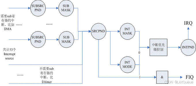
53个中断源被分成两种类型,一种是需要sub寄存器进行控制的,例如DMA,系统中的8个DMA中断是通过两级识别的,先在SRCPND寄存器中得到是DMA中断的信息,具体是哪一个channel的DMA中断需要继续查询SUBSRC寄存器。那些不需要sub寄存器进行控制的,例如timer,5个timer的中断可以直接从SRCPND中得到。
中断MASK寄存器可以控制产生的中断是否要报告给CPU,当一个中断被mask的时候,虽然SRCPND寄存器中,硬件会set该bit,但是不会影响到INTPND寄存器,从而不会向CPU报告该中断。对于SUBMASK寄存器,如果该bit被set,也就是该sub中断被mask了,那么即便产生了对应的sub中断,也不会修改SRCPND寄存器的内容,只是修改SUBSRCPND中寄存器的内容。
后续中断子系统文章详细介绍。
4.4、GPIO controller的处理
1. 设备树中 GPIO 控制器的描述
在设备树中,GPIO 控制器通常以以下结构描述:
dts
gpio_controller: gpio@12340000 {
    compatible = "vendor,model-gpio";
    reg = <0x12340000 0x1000>;
    gpio-controller;
    #gpio-cells = <2>;
    interrupt-controller;
    #interrupt-cells = <2>;
    interrupts = <5 0>;
    /* 其他特定于硬件的属性 */
};
解释:
gpio@12340000: 表示 GPIO 控制器的节点,通常包含控制器的硬件地址。compatible: 描述该控制器的型号和制造商,以便 Linux 内核能够选择合适的驱动程序。vendor,model-gpio是厂商和模型的名称。reg: 描述 GPIO 控制器的寄存器基地址和大小。通常是一个地址范围,内核通过这个信息访问控制器的寄存器。gpio-controller: 标识该设备是一个 GPIO 控制器。#gpio-cells: 通常设为<2>,表示设备树中定义 GPIO 引脚时需要两个单元:第一个单元是 GPIO 引脚的编号,第二个单元是 GPIO 配置。interrupt-controller: 如果 GPIO 控制器支持中断管理,这个属性会被设置。#interrupt-cells: 描述中断描述符的格式,通常为<2>。interrupts: 描述 GPIO 控制器的中断信息。
2. GPIO 驱动的初始化
GPIO 控制器驱动在内核中会注册为一个平台设备,平台设备描述了硬件设备以及它的资源。在设备树中定义的 gpio-controller 节点会与相应的 GPIO 驱动进行绑定。
驱动代码通常包括:
-
匹配设备树节点: 驱动会通过
of_match_node()或of_device_is_compatible()函数来查找设备树中的 GPIO 控制器节点。例如:
-
static const struct of_device_id gpio_of_match[] = { { .compatible = "vendor,model-gpio", }, { /* sentinel */ } }; -
初始化 GPIO 控制器: 驱动在初始化时会读取设备树中描述的资源(如
reg和interrupts)并初始化硬件。这个过程通常会在probe函数中完成。 -
static int gpio_probe(struct platform_device *pdev) { struct gpio_chip *gc; struct resource *res; int ret; gc = devm_kzalloc(&pdev->dev, sizeof(*gc), GFP_KERNEL); if (!gc) return -ENOMEM; res = platform_get_resource(pdev, IORESOURCE_MEM, 0); gc->base = res->start; /* 进一步配置GPIO硬件并初始化gpio_chip结构体 */ ret = devm_gpiochip_add_data(&pdev->dev, gc, NULL); if (ret) return ret; return 0; } -
GPIO 控制器的注册: 驱动会注册一个
gpio_chip结构体,该结构体包含了 GPIO 操作的回调函数(如设置、读取 GPIO 引脚的状态)。这些回调函数会实现对 GPIO 控制器的具体操作。例如: -
static const struct gpio_chip gpio_chip_ops = { .label = "gpio_chip", .direction_input = gpio_direction_input, .direction_output = gpio_direction_output, .get = gpio_get_value, .set = gpio_set_value, .request = gpio_request, /* 其他 GPIO 操作函数 */ }; -
GPIO 控制器的注册到内核: 通过
devm_gpiochip_add_data()函数将gpio_chip结构体注册到内核,这使得内核可以通过标准的 GPIO 接口来访问该控制器。 -
ret = devm_gpiochip_add_data(&pdev->dev, &gc, NULL);
if (ret) {
    dev_err(&pdev->dev, "Failed to register GPIO chip\n");
    return ret;
}
3. GPIO 的操作
一旦 GPIO 控制器初始化完成,内核就可以通过标准的 GPIO 接口进行操作。这些接口包括:
gpio_request():请求一个 GPIO 引脚。gpio_free():释放一个 GPIO 引脚。gpio_direction_input():设置 GPIO 引脚为输入。gpio_direction_output():设置 GPIO 引脚为输出。gpio_get_value():读取 GPIO 引脚的状态。gpio_set_value():设置 GPIO 引脚的状态。
这些接口允许驱动程序或用户空间应用程序通过文件系统或系统调用与 GPIO 控制器交互。
4. GPIO 中断
如果 GPIO 控制器支持中断功能,设备树中会包含 interrupt-controller 和 interrupts 属性。驱动程序将需要实现 GPIO 中断的处理:
-
注册中断: GPIO 控制器的驱动可以通过
request_irq()注册中断处理程序。 -
处理中断: 当 GPIO 引脚的电平变化或边沿触发中断时,中断处理程序会被调用。中断处理程序会执行相应的操作,通常是读取或写入 GPIO 引脚的状态。
5. GPIO 在设备树中的示例
假设一个设备的设备树如下所示:
dts
gpio@12340000 {
    compatible = "vendor,gpio-controller";
    reg = <0x12340000 0x1000>;
    gpio-controller;
    #gpio-cells = <2>;
    interrupt-controller;
    #interrupt-cells = <2>;
    interrupts = <5 0>;
    gpio-irq = <10>;
};
在这个例子中:
gpio-controller节点描述了一个 GPIO 控制器,基地址为0x12340000。#gpio-cells = <2>表示每个 GPIO 的描述需要两个单元,一个是 GPIO 引脚号,一个是 GPIO 配置。interrupts = <5 0>指示 GPIO 控制器可能会使用中断,使用中断 5。gpio-irq = <10>表示该 GPIO 控制器支持的中断源。
后续GPIO子系统文章详细介绍。
4.5、machine初始化
machine初始化的代码可以沿着start_kernel->rest_init->kernel_init->kernel_init_freeable->do_basic_setup->do_initcalls路径寻找。在do_initcalls函数中,kernel会依次执行各个initcall函数,在这个过程中,会调用customize_machine,具体如下:
arch/arm/kernel/setup.c
static int __init customize_machine(void)
{
	/*
	 * customizes platform devices, or adds new ones
	 * On DT based machines, we fall back to populating the
	 * machine from the device tree, if no callback is provided,
	 * otherwise we would always need an init_machine callback.
	 */
	if (machine_desc->init_machine)
		machine_desc->init_machine();

	return 0;
}
arch_initcall(customize_machine);
在这个函数中,一般会调用machine描述符中的init_machine callback函数来把各种Device Tree中定义的platform device设备节点加入到系统(即platform bus的所有的子节点,对于device tree中其他的设备节点,需要在各自bus controller初始化的时候自行处理)。如果machine描述符中没有定义init_machine函数,那么直接调用of_platform_populate把所有的platform device加入到kernel中。
例如RK3568
include/linux/rockchip/cpu.h
static inline bool cpu_is_rk3568(void)
{
	if (rockchip_soc_id)
		return (rockchip_soc_id & ROCKCHIP_CPU_MASK) == ROCKCHIP_CPU_RK3568;
	return of_machine_is_compatible("rockchip,rk3568");
}
drivers/of/base.c
/**
 * of_machine_is_compatible - Test root of device tree for a given compatible value
 * @compat: compatible string to look for in root node's compatible property.
 *
 * Returns a positive integer if the root node has the given value in its
 * compatible property.
 */
int of_machine_is_compatible(const char *compat)
{
	struct device_node *root;
	int rc = 0;

	root = of_find_node_by_path("/");
	if (root) {
		rc = of_device_is_compatible(root, compat);
		of_node_put(root);
	}
	return rc;
}
EXPORT_SYMBOL(of_machine_is_compatible);
platform device的代码来自of_platform_populate函数。该函数的逻辑比较简单,遍历device node global list中所有的node,并调用of_platform_bus_create处理,of_platform_bus_create函数代码如下:
drivers/of/platform.c
/**
 * of_platform_bus_create() - Create a device for a node and its children.
 * @bus: device node of the bus to instantiate
 * @matches: match table for bus nodes
 * @lookup: auxdata table for matching id and platform_data with device nodes
 * @parent: parent for new device, or NULL for top level.
 * @strict: require compatible property
 *
 * Creates a platform_device for the provided device_node, and optionally
 * recursively create devices for all the child nodes.
 */
static int of_platform_bus_create(struct device_node *bus,
				  const struct of_device_id *matches,
				  const struct of_dev_auxdata *lookup,
				  struct device *parent, bool strict)
{
	const struct of_dev_auxdata *auxdata;
	struct device_node *child;
	struct platform_device *dev;
	const char *bus_id = NULL;
	void *platform_data = NULL;
	int rc = 0;

	/* Make sure it has a compatible property */
	if (strict && (!of_get_property(bus, "compatible", NULL))) {
		pr_debug("%s() - skipping %pOF, no compatible prop\n",
			 __func__, bus);
		return 0;
	}

	/* Skip nodes for which we don't want to create devices */
	if (unlikely(of_match_node(of_skipped_node_table, bus))) {
		pr_debug("%s() - skipping %pOF node\n", __func__, bus);
		return 0;
	}

	if (of_node_check_flag(bus, OF_POPULATED_BUS)) {
		pr_debug("%s() - skipping %pOF, already populated\n",
			__func__, bus);
		return 0;
	}

	auxdata = of_dev_lookup(lookup, bus);
	if (auxdata) {
		bus_id = auxdata->name;
		platform_data = auxdata->platform_data;
	}

	if (of_device_is_compatible(bus, "arm,primecell")) {
		/*
		 * Don't return an error here to keep compatibility with older
		 * device tree files.
		 */
		of_amba_device_create(bus, bus_id, platform_data, parent);
		return 0;
	}

	dev = of_platform_device_create_pdata(bus, bus_id, platform_data, parent);
	if (!dev || !of_match_node(matches, bus))
		return 0;

	for_each_child_of_node(bus, child) {
		pr_debug("   create child: %pOF\n", child);
		rc = of_platform_bus_create(child, matches, lookup, &dev->dev, strict);
		if (rc) {
			of_node_put(child);
			break;
		}
	}
	of_node_set_flag(bus, OF_POPULATED_BUS);
	return rc;
}
具体增加platform device的代码在of_platform_device_create_pdata中,代码如下:drivers/of/platform.c
/**
 * of_platform_device_create_pdata - Alloc, initialize and register an of_device
 * @np: pointer to node to create device for
 * @bus_id: name to assign device
 * @platform_data: pointer to populate platform_data pointer with
 * @parent: Linux device model parent device.
 *
 * Returns pointer to created platform device, or NULL if a device was not
 * registered.  Unavailable devices will not get registered.
 */
static struct platform_device *of_platform_device_create_pdata(
					struct device_node *np,
					const char *bus_id,
					void *platform_data,
					struct device *parent)
{
	struct platform_device *dev;

	if (!of_device_is_available(np) ||
	    of_node_test_and_set_flag(np, OF_POPULATED))
		return NULL;

	dev = of_device_alloc(np, bus_id, parent);
	if (!dev)
		goto err_clear_flag;

	dev->dev.coherent_dma_mask = DMA_BIT_MASK(32);
	if (!dev->dev.dma_mask)
		dev->dev.dma_mask = &dev->dev.coherent_dma_mask;
	dev->dev.bus = &platform_bus_type;
	dev->dev.platform_data = platform_data;
	of_msi_configure(&dev->dev, dev->dev.of_node);

	if (of_device_add(dev) != 0) {
		platform_device_put(dev);
		goto err_clear_flag;
	}

	return dev;

err_clear_flag:
	of_node_clear_flag(np, OF_POPULATED);
	return NULL;
}


 3220
3220

 被折叠的 条评论
为什么被折叠?
被折叠的 条评论
为什么被折叠?
 到【灌水乐园】发言


