


 本文档详细介绍了如何在Raspberry Pi 3 Model B上安装和配置Android Things。首先,你需要准备一个8GB或更大的microSD卡、Micro-USB电缆和以太网线。然后,从Android Things控制台下载镜像并将其写入SD卡。接着,通过连接电源、以太网和可选的HDMI显示器来连接硬件。使用adb工具连接到设备的IP地址,并确保设备连接到Wi-Fi以接收更新。此外,文章还提到了串行控制台作为调试工具,以及Raspberry Pi 3的GPIO引脚配置和功能模式。
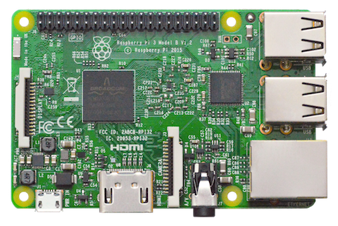
Raspberry Pi 3 Model B is the latest iteration of the world's most popular single
board computer. It provides a quad-core 64-bit ARM Cortex-A53 CPU running at
1.2GHz, four USB 2.0 ports, wired and wireless networking, HDMI and composite
video output, and a 40-pin GPIO connector for physical interfacing projects.
See the I/O pinouts for more details
on the Peripheral I/O signals on this
board.
Flashing the image
Before you begin flashing, you will need the following items in addition to your
Raspberry Pi:
Micro-USB cable
Ethernet cable
MicroSD card reader
8 GB or larger microSD card
Optional items:
HDMI cable
HDMI-enabled display
Step 1: Flash Android Things
Download an image from the Android Things Console
and write it to the microSD card:
Step 2: Connect the hardware
Make the following connections to your board:
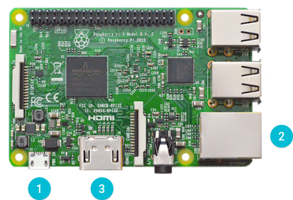
Connect a USB cable to J1 for power.
Connect an Ethernet cable to your local network.
Note:If you do not have wired access to your local network, you can do
either of the following:
Connect the Ethernet cable to your development computer and assign
the Raspberry Pi an IP address using DHCP.
Connect a serial cable from the Raspberry
Pi to your development computer. Use a serial console to connect to
Wi-Fi.
(Optional) Connect an HDMI cable to an external display.
Verify that Android is running on the device. To do this, you need to find
the IP address of the device:
If you connected a display, the Android Things Launcher will use it to
show information about the board, including the IP address.
If you assigned an IP address to the device using DHCP, find this
address in the network settings of your router or development computer.
Connect to the IP address using the adb tool:
$ adb connect
connected to :5555
Note:Raspberry Pi broadcasts the hostname Android.local over Multicast DNS.
If your host platform supports MDNS, you can also connect to the board using
the following command:
$ adb connect Android.local
Connect Wi-Fi
After flashing your board, it is strongly recommended to connect it to
the internet. This allows your device to deliver crash reports and receive updates.
Note:The device doesn't need to be on the same network as your computer.
To connect to Wi-Fi, follow the instructions to
connect to Wi-Fi with adb.
Serial debug console
The serial console is a helpful tool for debugging your board and reviewing
system log information. The console is the default output location for kernel
log messages (i.e. dmesg), and it also provides access to a full shell prompt
that you can use to access commands such as logcat.
This is helpful if you are unable to access ADB on your board through other
means and have not yet enabled a network connection.
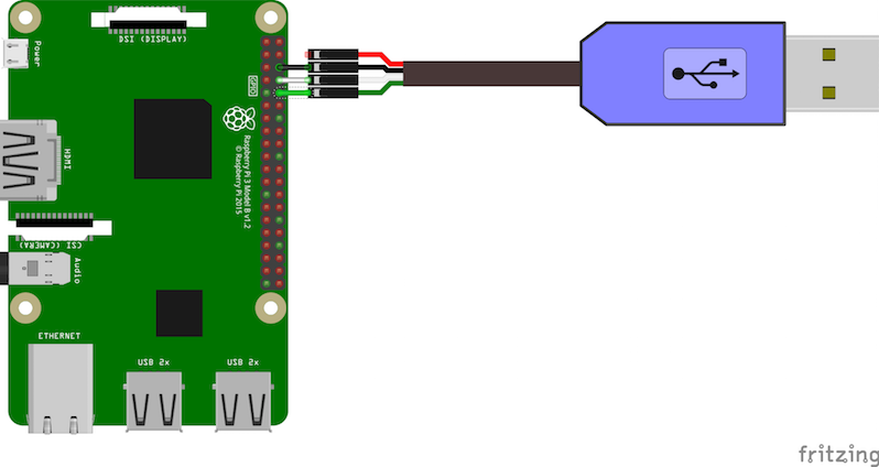
To access the serial console, connect a USB to TTL Serial
Cable to the device UART pins as shown
below.
Open a connection to the USB serial device on your development computer using a
terminal program, such as PuTTY (Windows),
Serial (Mac OS), or
Minicom (Linux). The serial port
parameters for the console are as follows:
Baud Rate: 115200
Data Bits: 8
Parity: None
Stop Bits: 1
I/O Pinouts
This section describes the Peripheral I/O
interfaces available to your apps running on the
Raspberry Pi 3.
The Raspberry Pi has pins that are multiplexed between various board functions.
Some board functions cannot be used simultaneously (for example, enabling
Bluetooth and using the UART0 port for peripheral I/O). For more information,
see the pin function modes.
Note:You can use the PIO CLI Tool to
do simple test operations on these interfaces.
The following pinout diagram illustrates the locations of the available ports
exposed by the breakout connectors of this board:
GPIO Signal
Alternate Functions
BCM2I2C1 (SDA)
BCM3I2C1 (SCL)
BCM7SPI0 (SS1)
BCM8SPI0 (SS0)
BCM9SPI0 (MISO)
BCM10SPI0 (MOSI)
BCM11SPI0 (SCLK)
BCM13PWM1
BCM14UART0 (TXD)MINIUART (TXD)
BCM15UART0 (RXD)MINIUART (RXD)
BCM18I2S1 (BCLK)PWM0
BCM19I2S1 (LRCLK)
BCM20I2S1 (SDIN)
BCM21I2S1 (SDOUT)
Pin Function Modes
The following modes in each table are mutually exclusive on the Raspberry Pi
3.
UART modes
The Raspberry Pi has a single full-speed UART (UART0) and a mini UART
(MINIUART); see the official docs
for information on their differences. These UARTs are multiplexed
between various board functions and cannot be used simultaneously. The following
modes are supported:
Mode
Activated By
Bluetooth
Pin Functions
Debug console
Default mode; no PIO connections
Enabled
Pins BCM14/BCM15 expose RX/TX of the serial debug console
UART0
UART0 opened by PIO
Disabled
Pins BCM14/BCM15 expose RX/TX of UART0
MINIUART
MINIUART opened by PIO
Enabled
Pins BCM14/BCM15 expose RX/TX of MINIUART
BCM14 or BCM15
Pin opened by PIO
Enabled
Named pin (BCM14 or BCM15) is GPIO, other pin is idle
An IOException error is thrown if you try to open an active pin (from above)
using a different UART mode.
Note:Switching back to Debug console mode after opening a pin (with a PIO
connection) requires a device reboot.
Audio modes
The Raspberry Pi shares hardware resources between Peripheral I/O and the audio
subsystem (I2S and analog). Analog audio is transmitted through the 3.5mm audio
jack. The following modes are supported:
Mode
Activated By
Audio Routes
Pin Functions
Audio
Default mode; no PIO connections
I2S + Analog
N/A
PWM
PWM0 opened by PIO
Disabled
Pin BCM18 enabled as PWM
GPIO
Pin
Analog only
Named pin is GPIO
1 Includes pins BCM18, BCM19, BCM20, and BCM21
Note:Switching back to Audio mode requires a device reboot due to
limitations of the hardware.
When you are creating a hardware configuration in the
Android Things Console, BCM18 and BCM19
pullup and pulldown resistors don't apply until the GPIO is actually
opened in order to avoid interfering with the I2S bus on the same pins.


 2077
2077

 被折叠的 条评论
为什么被折叠?
被折叠的 条评论
为什么被折叠?
 到【灌水乐园】发言


