


 本文介绍了一种使用OpenCV计算图像中两条曲线间距离的方法。通过添加切线并找到90度法线来确定距离,提供了详细的C++代码示例及Python应用建议。
http://answers.opencv.org/question/129819/finding-distance-between-two-curves/
问题:
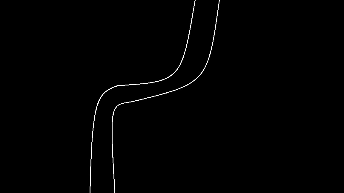
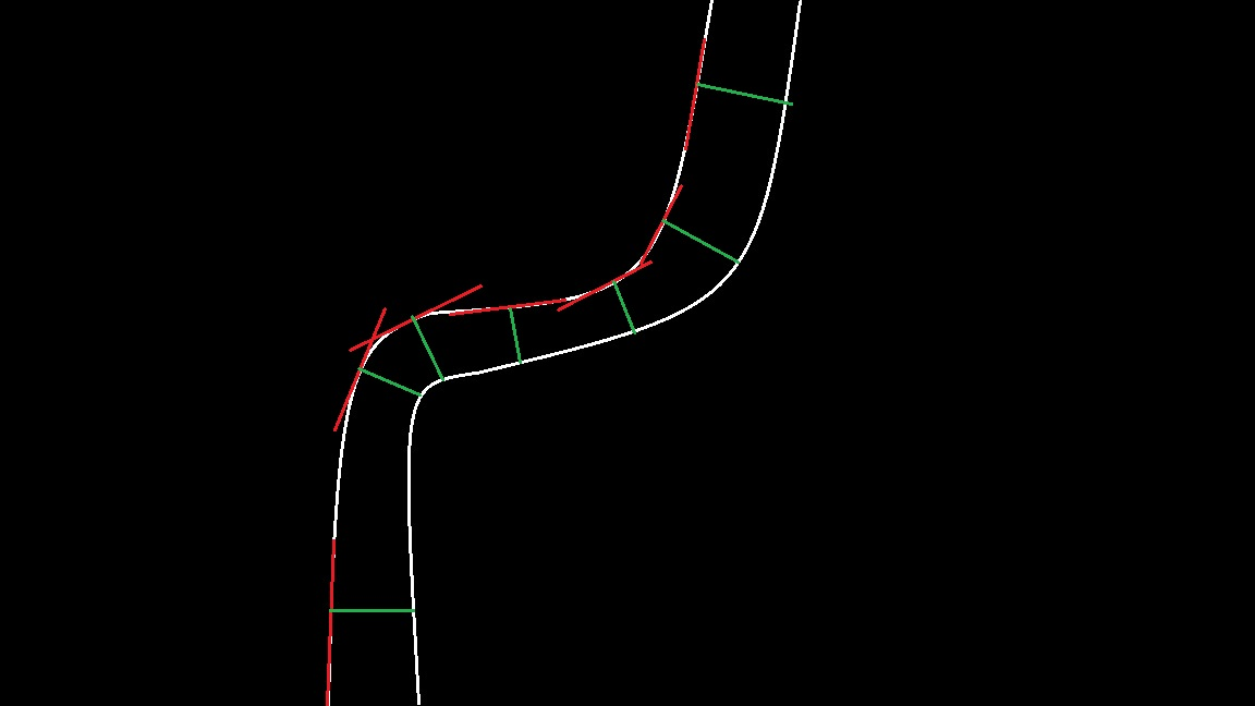
Hello, Im trying to add tangents along the curve in the image below, like the red lines in the second picture. Then I would like to use the tangents to find the the 90 degrees normal line to the tangent(the green lines).
The goal is to find the distance between the two white lines at different places. I use Python and if anyone have any suggestion on how I could do this, or have any suggestions of a better way, I would be very grateful.
优质解答:
I think this example in C++ should work. Unfortunately I don't know Python DistanceTranform but I think you can use this tutorial in
C++ and this one in
python to translate it in python. SparseMatrix is only for fun. you don't need it result (in Mat result) is saved in an yml file.
int main(
int argc,
char
* argv[])
{
Mat img =imread( "14878460214049233.jpg",IMREAD_GRAYSCALE);
imshow( "test",img);
threshold(img,img, 200, 255,CV_THRESH_BINARY); // to delete some noise
imshow( "test", img);
Mat labels;
connectedComponents(img,labels, 8,CV_16U);
Mat result(img.size(),CV_32FC1,Scalar : :all( 0));
for ( int i = 0; i < = 1; i ++)
{
Mat mask1 = labels == 1 +i;
Mat mask2 = labels == 1 +( 1 -i);
Mat masknot;
bitwise_not(mask1,masknot);
imshow( "masknot", masknot);
Mat dist;
distanceTransform(masknot,dist, DIST_L2, 5,CV_8U);
imshow( "distance float", dist / 255);
dist.copyTo(result,mask2);
}
imshow( "distance 1",result);
FileStorage fs( "distCtr.yml",FileStorage : :WRITE);
fs << "Image" <<result;
fs.release();
waitKey();
SparseMat ms(result);
SparseMatConstIterator_ < float > it = ms.begin < float >(),it_end = ms.end < float >();
Mat lig(result.rows, 1,CV_8U,Scalar : :all( 0));
for (; it != it_end; it ++)
{
// print element indices and the element value
const SparseMat : :Node * n = it.node();
if (lig.at <uchar >(n - >idx[ 0]) == 0)
{
cout << "(" <<n - >idx[ 0] << "," <<n - >idx[ 1] << ") = " <<it.value < float >() << "\t";
lig.at <uchar >(n - >idx[ 0]) = 1;
}
}
return 0;
}
{
Mat img =imread( "14878460214049233.jpg",IMREAD_GRAYSCALE);
imshow( "test",img);
threshold(img,img, 200, 255,CV_THRESH_BINARY); // to delete some noise
imshow( "test", img);
Mat labels;
connectedComponents(img,labels, 8,CV_16U);
Mat result(img.size(),CV_32FC1,Scalar : :all( 0));
for ( int i = 0; i < = 1; i ++)
{
Mat mask1 = labels == 1 +i;
Mat mask2 = labels == 1 +( 1 -i);
Mat masknot;
bitwise_not(mask1,masknot);
imshow( "masknot", masknot);
Mat dist;
distanceTransform(masknot,dist, DIST_L2, 5,CV_8U);
imshow( "distance float", dist / 255);
dist.copyTo(result,mask2);
}
imshow( "distance 1",result);
FileStorage fs( "distCtr.yml",FileStorage : :WRITE);
fs << "Image" <<result;
fs.release();
waitKey();
SparseMat ms(result);
SparseMatConstIterator_ < float > it = ms.begin < float >(),it_end = ms.end < float >();
Mat lig(result.rows, 1,CV_8U,Scalar : :all( 0));
for (; it != it_end; it ++)
{
// print element indices and the element value
const SparseMat : :Node * n = it.node();
if (lig.at <uchar >(n - >idx[ 0]) == 0)
{
cout << "(" <<n - >idx[ 0] << "," <<n - >idx[ 1] << ") = " <<it.value < float >() << "\t";
lig.at <uchar >(n - >idx[ 0]) = 1;
}
}
return 0;
}
解读:
1、取反,比用threshthold方便;
bitwise_not
(mask1,masknot);
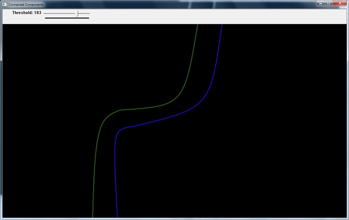
2、connectedComponents 寻找联通区域
官方解释和例子:
| int cv::connectedComponents | ( | InputArray | image, |
| OutputArray | labels, | ||
| int | connectivity = 8, | ||
| int | ltype = CV_32S | ||
| ) |
computes the connected components labeled image of boolean image
image with 4 or 8 way connectivity - returns N, the total number of labels [0, N-1] where 0 represents the background label. ltype specifies the output label image type, an important consideration based on the total number of labels or alternatively the total number of pixels in the source image.
-
Parameters
-
image the 8-bit single-channel image to be labeled labels destination labeled image connectivity 8 or 4 for 8-way or 4-way connectivity respectively ltype output image label type. Currently CV_32S and CV_16U are supported.
#
include
<opencv2
/core
/utility.hpp
>
# include "opencv2/imgproc.hpp"
# include "opencv2/imgcodecs.hpp"
# include "opencv2/highgui.hpp"
# include <iostream >
using namespace cv;
using namespace std;
Mat img;
int threshval = 100;
static void on_trackbar( int, void *)
{
Mat bw = threshval < 128 ? (img < threshval) : (img > threshval);
Mat labelImage(img.size(), CV_32S);
int nLabels = connectedComponents(bw, labelImage, 8);
std : :vector <Vec3b > colors(nLabels);
colors[ 0] = Vec3b( 0, 0, 0); //background
for( int label = 1; label < nLabels; ++label){
colors[label] = Vec3b( (rand() & 255), (rand() & 255), (rand() & 255) );
}
Mat dst(img.size(), CV_8UC3);
for( int r = 0; r < dst.rows; ++r){
for( int c = 0; c < dst.cols; ++c){
int label = labelImage.at < int >(r, c);
Vec3b &pixel = dst.at <Vec3b >(r, c);
pixel = colors[label];
}
}
imshow( "Connected Components", dst );
}
static void help()
{
cout << "\n This program demonstrates connected components and use of the trackbar\n"
"Usage: \n"
" ./connected_components <image(../data/stuff.jpg as default)>\n"
"The image is converted to grayscale and displayed, another image has a trackbar\n"
"that controls thresholding and thereby the extracted contours which are drawn in color\n";
}
const char * keys =
{
"{help h||}{@image|../data/stuff.jpg|image for converting to a grayscale}"
};
int main( int argc, const char * * argv )
{
CommandLineParser parser(argc, argv, keys);
if (parser.has( "help"))
{
help();
return 0;
}
string inputImage = "twolines.jpg";
img = imread(inputImage.c_str(), 0);
if(img.empty())
{
cout << "Could not read input image file: " << inputImage << endl;
return - 1;
}
namedWindow( "Image", 1 );
imshow( "Image", img );
namedWindow( "Connected Components", 1 );
createTrackbar( "Threshold", "Connected Components", &threshval, 255, on_trackbar );
on_trackbar(threshval, 0);
waitKey( 0);
return 0;
}
但这个例子说不清楚,我自己做一个例子,3条线
connectedComponents(img,labels,
8,CV_16U);
....
Mat tmp = labels == 1;
Mat tmp2 = labels == 2;
Mat tmp3 = labels == 3;
....
Mat tmp = labels == 1;
Mat tmp2 = labels == 2;
Mat tmp3 = labels == 3;
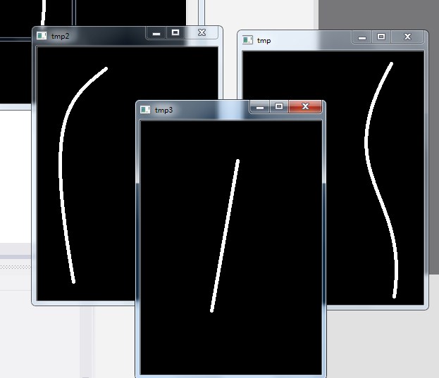
结果3个联通区域都能够找出来。这个函数之前我不知道,找联通区域是自己写函数实现的。
3、 Mat result(img.size(),CV_32FC1,Scalar::all(0));
这句就是生成全白的图片。应该说Mat::ones一直都不好用,采用直接定义的方式应该是正确的方式。
补一下数据格式
• CV_8U
-
8
-bit
unsigned integers (
0..
255 )
• CV_8S - 8 -bit signed integers ( - 128.. 127 )
• CV_16U - 16 -bit unsigned integers ( 0.. 65535 )
• CV_16S - 16 -bit signed integers ( - 32768.. 32767 )
• CV_32S - 32 -bit signed integers ( - 2147483648.. 2147483647 )
• CV_32F - 32 -bit floating -point numbers ( -FLT_MAX..FLT_MAX, INF, NAN )
• CV_64F - 64 -bit floating -point numbers ( -DBL_MAX..DBL_MAX, INF, NAN )
4、
distanceTransform
(masknot,dist, DIST_L2,5,CV_8U);
首先对图像进行二值化处理,然后给每个像素赋值为离它最近的背景像素点与其距离(Manhattan距离or欧氏距离),得到distance metric(距离矩阵),那么离边界越远的点越亮。
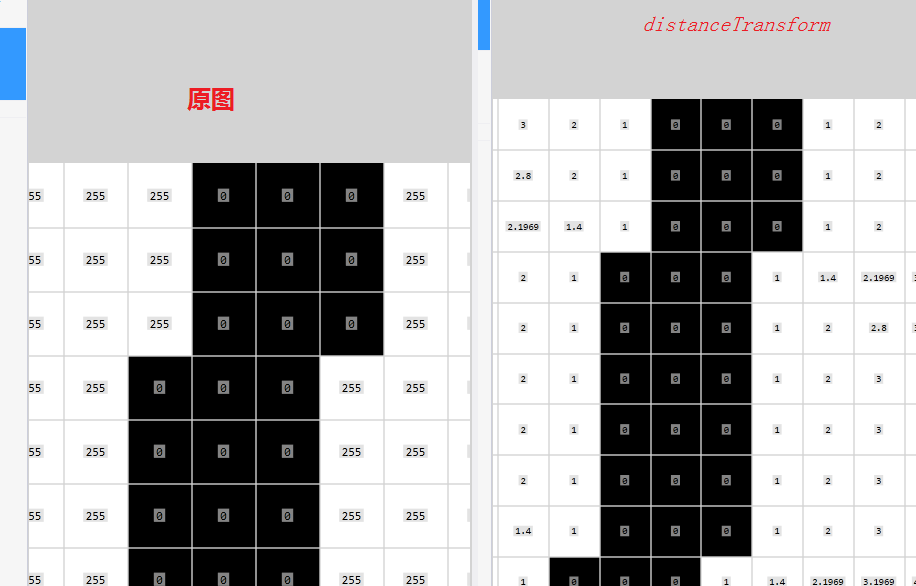
这个图就能够很好地表示出来。注意在OpenCV中始终是以黑色作为0,也是作为背景的。
5、
dist
.
copyTo
(
result
,
mask2
);
带有mask的copy,用法都是平时比较少用的。mask的含义就是只有在mask为255的地方,这个拷贝才有效。
6、最为核心的地方到了,这个地方写得非常巧妙
for (
int i
=
0; i
<
=
1; i
++)
{
Mat mask1 = labels == 1 +i;
Mat mask2 = labels == 1 +( 1 -i);
Mat masknot;
bitwise_not(mask1,masknot);
imshow( "masknot", masknot);
Mat dist;
distanceTransform(masknot,dist, DIST_L2, 5,CV_8U);
imshow( "distance float", dist / 255);
dist.copyTo(result,mask2);
}
{
Mat mask1 = labels == 1 +i;
Mat mask2 = labels == 1 +( 1 -i);
Mat masknot;
bitwise_not(mask1,masknot);
imshow( "masknot", masknot);
Mat dist;
distanceTransform(masknot,dist, DIST_L2, 5,CV_8U);
imshow( "distance float", dist / 255);
dist.copyTo(result,mask2);
}
循环两次,只看一次,在第一次中
mask1 是左边这条线
mask2 是右边这条线
那么,直接mask1做bitwise_not翻转之后,这个时候,mask1上面的这条线是黑色的(0)而背景是白色的(255),
distanceTransform计算,那么得到了图像上所有白色区域到这条线的距离。
为了把mask2这条线显示出来,直接以mask2为模板,把dist copyto到新的mat里面
去,那么留下来的就是mask2上所有到mask1的距离值。
非常巧妙,我领悟了半天才明白,赞叹赞叹!
7、
SparseMat 稀疏矩阵
如果是我做的话,做到这一步可能就直接打印了,但是回答者继续一步
稀疏矩阵意味着只有非0元素会被存储
SparseMat ms(result);
SparseMatConstIterator_ < float > it = ms.begin < float >(),it_end = ms.end < float >();
Mat lig(result.rows, 1,CV_8U,Scalar : :all( 0));
for (; it != it_end; it ++)
{
// print element indices and the element value
const SparseMat : :Node * n = it.node();
if (lig.at <uchar >(n - >idx[ 0]) == 0)
{
cout << "(" <<n - >idx[ 0] << "," <<n - >idx[ 1] << ") = " <<it.value < float >() << "\t";
lig.at <uchar >(n - >idx[ 0]) = 1;
}
}
这段代码也非常棒!它的目的是每一行只取一个值,并且打印出来。
当然,如果资源不成问题的话,直接采用原图循环的方法也很直接。但是我详细稀疏矩阵应该有独特的应用吧。
整个解答,思路清晰,代码富有弹性。


 1280
1280

 被折叠的 条评论
为什么被折叠?
被折叠的 条评论
为什么被折叠?
 到【灌水乐园】发言


