


 本文介绍如何在 STM32F4xx 微控制器上使用 ARM 提供的数学库实现 PID 控制器。通过两个 DS18B20 温度传感器和一个直流风扇的实例演示了 PID 控制的应用。
Project 03- STM32F4xx PID controller
CMSIS files from ARM provides ARM Math functions.
There are also PID controller functions in different formats for f32, q31 and q7.
This tutorial/project will talk about how to implement PID controller on STM32F4xx using PID functions from ARM.
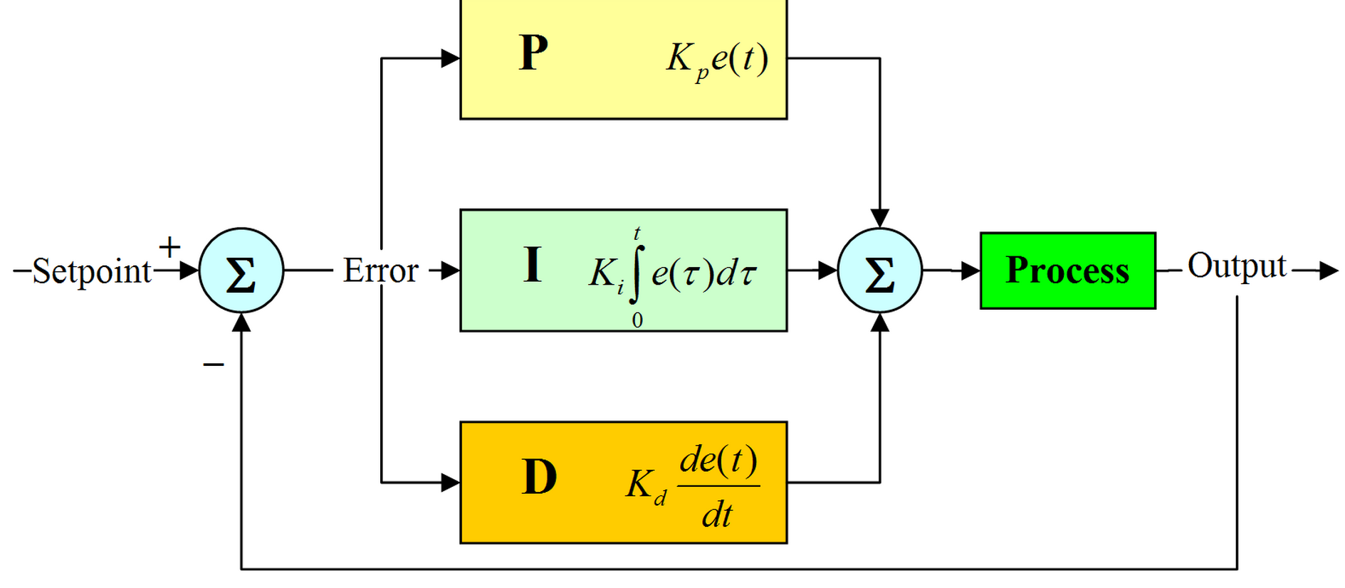
PID Controller
Fast about PID controller.
PID stands for Proportional-Integral-Derivative controller.
This is a control loop feedback mechanism widely used in industrial control systems.
It calculates the error between measured value and the desired setpoint value.
According to the error, it then calculates output value to minimize this error.
I will not go step-by-step on how PID works. More you can look on the sites below:
ARM PID library
ARM company provides 3 different PID controller functions:
- f32: float
- q31: integer
- q7: char
For each of the three types, you have three functions:
- f32
- arm_pid_init_f32
- arm_pid_reset_f32
- arm_pid_f32
- q31
- arm_pid_init_q31
- arm_pid_reset_q31
- arm_pid_q31
- q7
- arm_pid_init_q7
- arm_pid_reset_q7
- arm_pid_q7
There are also ARM PID structure, where you pass PID parameters.
More in project example below.
If you need additional info about these functions, you have detailed manual here.
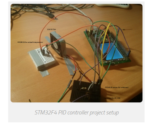
PID Sample project
In the project, 2 DS18B20 temperature sensors are used.
They are configured in 12bit resolution, so delay between 2 calculations is about ~750ms.
If you read about PID controller, you realize that you cannot calculate PID controller results every x microcontroller,
because it has integral part which is used to sum all the errors in period.
More calculations you have, more integral error you have.
We have one device connected as “reference” temperature.
Second sensor is placed near DC FAN,
so when DC fan is turned ON, it is cooling the second DS18B20.
The goal is, that both temperatures are the same.
In my case, it was about 23°C on the reference sensor.
Then, I touched the second DS18B20 near DC fan and I heated them. DC fan was turned on.
Everything is displayed via USART to computer.
FAN is controlled via 1kHz PWM output.
According to the error between both sensors, more error, more duty cycle to DC fan.
This is just a sample project, so PID parameters are not set optimal.
For every project you have to set parameters for specific project.
This example successfully works on all STM32F4xx development board such as Discovery and Nucleo.
In the example, 1 PID controller is used.
If you need to control more than just one thing,
you can add additional ARM PID instances and
you can use more than just one PID controller at a time.
Pinout
- Both DS18B20 sensors are connected to the same pin: PA6
- DC fan PWM pin (controlled via transistor): PA5
- USART output: PB6, 115200baud
Example
/**
 *    Keil project for DS18B20 & ARM PID example
 *
 *    Before you start, select your target, on the right of the "Load" button
 *
 *    @author        Tilen Majerle
 *    @email        tilen@majerle.eu
 *    @website    http://stm32f4-discovery.com
 *    @ide        Keil uVision 5
 *    @packs        STM32F4xx Keil packs version 2.2.0 or greater required
 *    @stdperiph    STM32F4xx Standard peripheral drivers version 1.4.0 or greater required
 *
 *    Additional defines in "Options for Target" > "C/C++" > "Defines"
 *        - ARM_MATH_CM4
 *        - __FPU_PRESENT = 1
 */
/* Include core modules */
#include "stm32f4xx.h"
/* Include my libraries here */
#include "defines.h"
#include "tm_stm32f4_delay.h"
#include "tm_stm32f4_onewire.h"
#include "tm_stm32f4_ds18b20.h"
#include "tm_stm32f4_disco.h"
#include "tm_stm32f4_usart.h"
#include "tm_stm32f4_pwm.h"
#include <stdio.h>

/* Include ARM math */
#include "arm_math.h"

/* How many sensors we are expecting on 1wire bus? */
#define EXPECTING_SENSORS    2

#define TEMP_CURRENT        temps[1]    /* Temperature we actually have */
#define TEMP_WANT            temps[0]    /* Temperature we want to have */

/* Choose PID parameters */
#define PID_PARAM_KP        100            /* Proporcional */
#define PID_PARAM_KI        0.025        /* Integral */
#define PID_PARAM_KD        20            /* Derivative */

int main(void) {
    /* Timer data for PWM */
    TM_PWM_TIM_t TIM_Data;
    char buf[150];
    uint8_t devices, i, count;
    /* DS18B20 devices ID */
    uint8_t device[EXPECTING_SENSORS][8];
    /* Temperatures from 2 sensors */
    float temps[EXPECTING_SENSORS];
    /* PID error */
    float pid_error;
    /* Duty cycle for PWM */
    float duty = 0;
    /* ARM PID Instance, float_32 format */
    arm_pid_instance_f32 PID;
    /* One wire instance */
    TM_OneWire_t OneWire;

    /* Set PID parameters */
    /* Set this for your needs */
    PID.Kp = PID_PARAM_KP;        /* Proporcional */
    PID.Ki = PID_PARAM_KI;        /* Integral */
    PID.Kd = PID_PARAM_KD;        /* Derivative */

    /* Initialize PID system, float32_t format */
    arm_pid_init_f32(&PID, 1);

    /* Initialize system */
    SystemInit();

    /* Initialize delay */
    TM_DELAY_Init();

    /* Initialize Leds */
    TM_DISCO_LedInit();

    /* Initialize USART1, TX: PB6, 115200 baud */
    TM_USART_Init(USART1, TM_USART_PinsPack_2, 115200);

    /* Initialize TIM2, 1kHz frequency */
    TM_PWM_InitTimer(TIM2, &TIM_Data, 1000);

    /* Initialize TIM2, Channel 1, PinsPack 2 = PA5 */
    TM_PWM_InitChannel(&TIM_Data, TM_PWM_Channel_1, TM_PWM_PinsPack_2);

    /* Set default duty cycle */
    TM_PWM_SetChannelPercent(&TIM_Data, TM_PWM_Channel_1, duty);

    /* Initialize OneWire, pin PA6 */
    TM_OneWire_Init(&OneWire, GPIOA, GPIO_PIN_6);

    /* Checks for any device on 1-wire */
    count = 0;
    devices = TM_OneWire_First(&OneWire);
    while (devices) {
        /* Get full ROM value, 8 bytes, give location of first byte where to save */
        TM_OneWire_GetFullROM(&OneWire, device[count]);
        /* Increase count for devices */
        count++;
        /* Get next device */
        devices = TM_OneWire_Next(&OneWire);
    }

    /* We need 2 devices */
    if (count != 2) {
        TM_USART_Puts(USART1, "We expect 2 devices on 1-wire. Quiting!\n");

        /* While */
        while (1);
    }

    /* Go through all connected devices and set resolution to 12bits */
    for (i = 0; i < count; i++) {
        TM_DS18B20_SetResolution(&OneWire, &device[i][0], TM_DS18B20_Resolution_12bits);
    }

    /* Start temperature conversion on all devices */
    TM_DS18B20_StartAll(&OneWire);

    while (1) {
        /* If all sensors are done with conversion */
        /* This will happen about every 750ms, because DS18B20 needs ~750ms for conversion in 12bit resolution mode */
        if (TM_DS18B20_AllDone(&OneWire)) {
            /* Read temperature 1, reference temperature */
            TM_DS18B20_Read(&OneWire, device[0], &TEMP_WANT);

            /* Read temperature 2, actual temperature */
            TM_DS18B20_Read(&OneWire, device[1], &TEMP_CURRENT);

            /* Start new temperature conversion on all devices */
            TM_DS18B20_StartAll(&OneWire);

            /* Set LEDs according to the which temperature is higher */
            if (TEMP_CURRENT > TEMP_WANT) {
                TM_DISCO_LedOn(LED_GREEN);
                TM_DISCO_LedOff(LED_RED);
            } else if (TEMP_CURRENT < TEMP_WANT) {
                TM_DISCO_LedOn(LED_RED);
                TM_DISCO_LedOff(LED_GREEN);
            } else {
                TM_DISCO_LedOff(LED_ALL);
            }

            /* Calculate error */
            pid_error = TEMP_CURRENT - TEMP_WANT;

            /* Calculate PID here, argument is error */
            /* Output data will be returned, we will use it as duty cycle parameter */
            duty = arm_pid_f32(&PID, pid_error);

            /* Check overflow, duty cycle in percent */
            if (duty > 100) {
                duty = 100;
            } else if (duty < 0) {
                duty = 0;
            }

            /* Set PWM duty cycle for DC FAN to cool down sensor for "TEMP_CURRENT" */
            TM_PWM_SetChannelPercent(&TIM_Data, TM_PWM_Channel_1, duty);

            /* Format string */
            sprintf(buf, "Expected:   %2.3f C\nActual:     %2.3f C\nError:      %2.3f C\nDuty cycle: %3.2f %%\n----\n", TEMP_WANT, TEMP_CURRENT, pid_error, duty);

            /* Send to USART */
            TM_USART_Puts(USART1, buf);
        }
    }
}
2 PID controller
2.1 Description
The proportional-integral-derivative or PID controller is commonly used in the industry.
It is a feedback loop controller that manages the process command with a view to reducing the error
between the desired set point and the measured process variable.
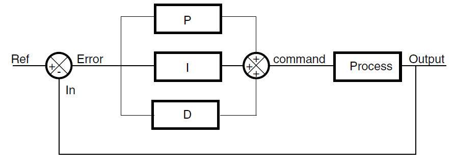
The following block diagram shows the parallel structure of a PID controller.
This is the structure implemented in this DSP library.
Figure 1. Block diagram of PID controller
DSP library functions
The DSP library provides three PID functions:
● DoPID: a PID core loop coded in C (the error is computed outside the function)
● DoFullPID: a full PID controller coded in C (with error computing)
● PID_stm32: an optimized PID core loop written in assembly


 2214
2214

 被折叠的 条评论
为什么被折叠?
被折叠的 条评论
为什么被折叠?
 到【灌水乐园】发言


