


 本文详细介绍了J2534标准,包括其不同版本的功能定义与扩展特性,如Pass-Thru设备如何连接车辆网络并进行通信。此外,还阐述了通过J2534 API实现车辆模块重新编程的方法及支持的各种协议。


Connects to the OBDII J1962 DLC and supports the following protocols.
1 CAN2 Single Wire
2 J1850PWM+ , J1850VPW
3 CAN2+
6 CAN+ (CAN-C only), SCI A Engine, 5v-20v out
7 ISO-9141 K-line, SCI A Engine, SCI A Trans, SCI B Engine
9 SCI B Trans, 5v-20v out or short-to-ground
10 J1850PWM-
11 CAN2- 5v-20v out
12 SCI B Engine 5v-20v out or short-to-ground
14 CAN- (CAN-C only), SCI A Trans 5v-20v out
15 ISO L Line, SCI B Trans, Short-to-ground

The PassThru device manufacturer supplies the hardware appliance and cable that connects to and communicates with the vehicle network.
The physical interface to the vehicle network is the SAE J1962 connector, which supports the various vehicle serial data protocols.
The following network layer protocols are supported:
ISO 9141
ISO 14230-4(KWP2000, Keyword Protocol)
SAE J1850 41.6 KBPS PWM(Pulse Width Modulation)
SAE J1850 10.4 KBPS VPW(Variable Pulse Width)
CAN(Controller Area Network, ISO 11898)
ISO 15765-4(CAN)
SAE J2610 DaimlerChrysler SCI(Serial Communications Interface)
J2534-1: Recommended Practice for Pass-Thru Vehicle Programming Last published version 12/2004
J2534-2: Optional Pass-Thru Features Last published version 04/2010
J2534-3: Conformance Test Cases for an SAE J2534-1 Device No published document
SAE J2534-1
defines an Application Program Interface (API) that can be used by Vehicle Manufacturers for reprogramming emission related modules.
This interface also includes some capabilities that may not be required for reprogramming,
but allows the interface to be used for other purposes without placing a significant burden on the interface manufacturers.
SAE J2534-2
defines optional features that takes advantage of the J2534-1 framework.
It allows the interface (J2534) to be used for other purposes and includes features that are above and beyond emission related reprogramming needs.
Many OEM’s wanted a standard for reprogramming other modules not “Emission Related”.
Those instructions were added into -2. It also expands the scope of what a J2534 device can do. (ie: Diagnostics)
SAE J2534-3
defines a set of conformance test cases, which can be used to check an interface’s compliance with SAE J2534-1 Conformance test cases are planned for J2534-2 features
also Some preliminary work has been done on the J2534-1 conformance test cases.
No work has been initiated for the J2534-2 conformance test cases.
There is no published standard yet.
J2534 framework includes application interfaces for the following functionality:
Network Initialization
Basic Send and Receive
Periodic Transmission Capability
Message Filters
Generic IO Control
Protocol Specific IO Control
Programming Voltage Supply
Other Utility Functions
Protocols Supported by a fully compliant SAE J2534-1 Device
J1850 VPW (GM Class2, Chrysler OBD)
J1850 PWM (Ford SCP)
High Speed CAN ISO 15765-4 (Diag. On CAN)
ISO 14230 (KWP)
ISO 9141-2
Chrysler SCI
Additional Protocols Currently Supported by the SAE J2534-2 Specifications
SAE J1939
SAE J1708
Single Wire CAN
GM UART
UART Echo Byte
Ford MS-CAN
Honda Diag-H
TP 2.0
Fault Tolerant CAN
6.5.1 ISO 9141
The following specifications clarify and, if in conflict with ISO 9141, override any related specifications in ISO 9141:
a. The maximum sink current to be supported by the interface is 100 mA.
b. The range for all tests performed relative to ISO 7637-1 is –1.0 to +40.0 V.
c. The default bus idle period before the interface shall transmit an address, shall be 300 ms.
d. Support following baud rate with ±0.5% tolerance: 10400.
e. Support following baud rate with ±1% tolerance: 10000.
f. Support following baud rates with ±2% tolerance: 4800, 9600, 9615, 9800, 10870, 11905, 12500, 13158, 13889, 14706, 15625, and 19200.
g. Support other baud rates if the interface is capable of supporting the requested value within ±2%.
h. The baud rate shall be set by the application, not determined by the SAE J2534 interface. The interface is not required to support baud rate detection based on the synchronization byte.
i. Support odd and even parity in addition to the default of no parity, with seven or eight data bits. Always one start bit and one stop bit.
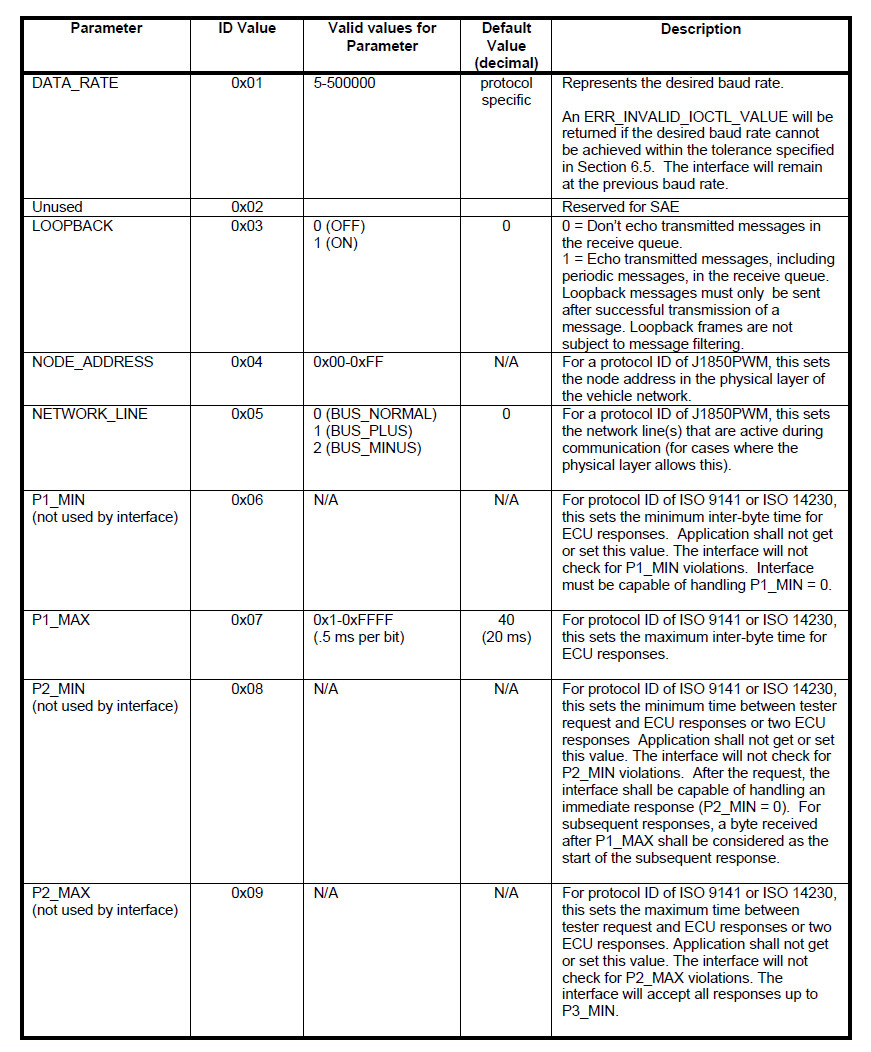
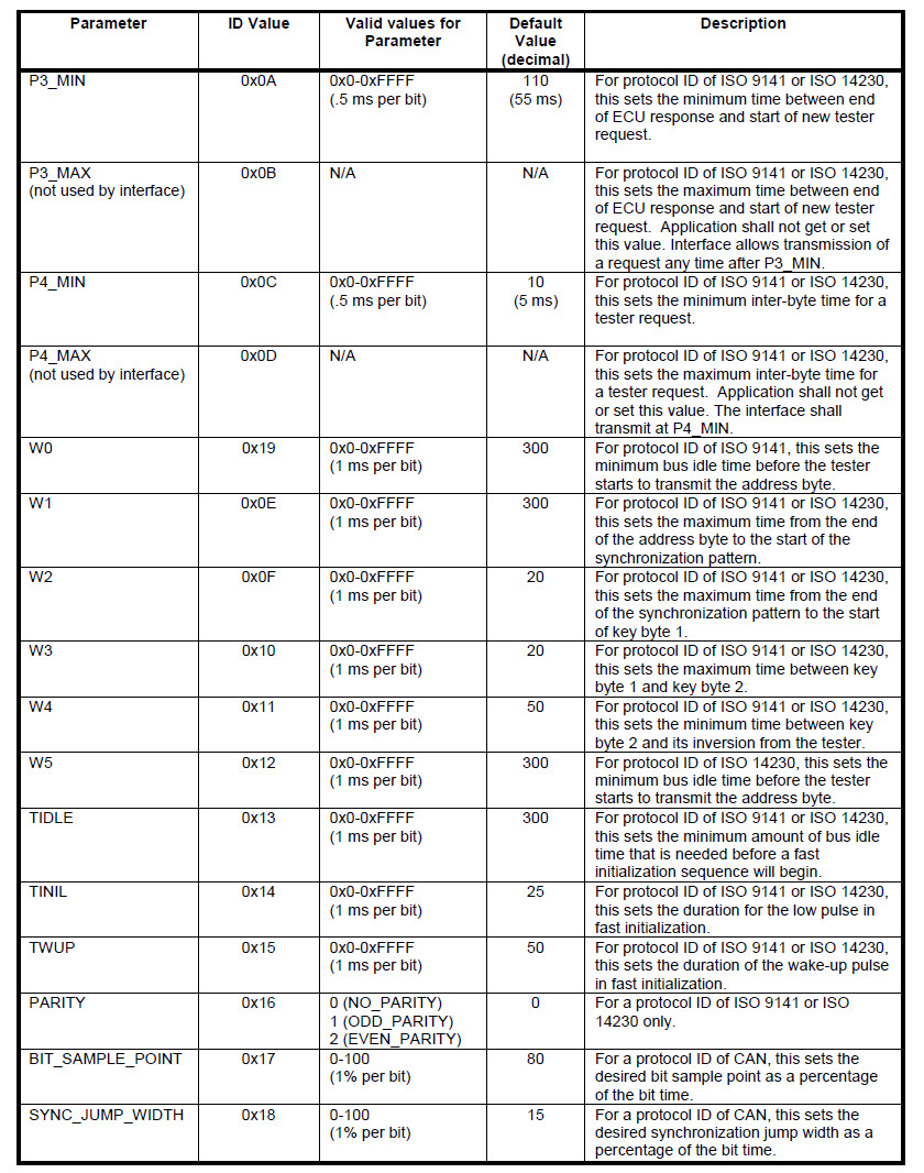
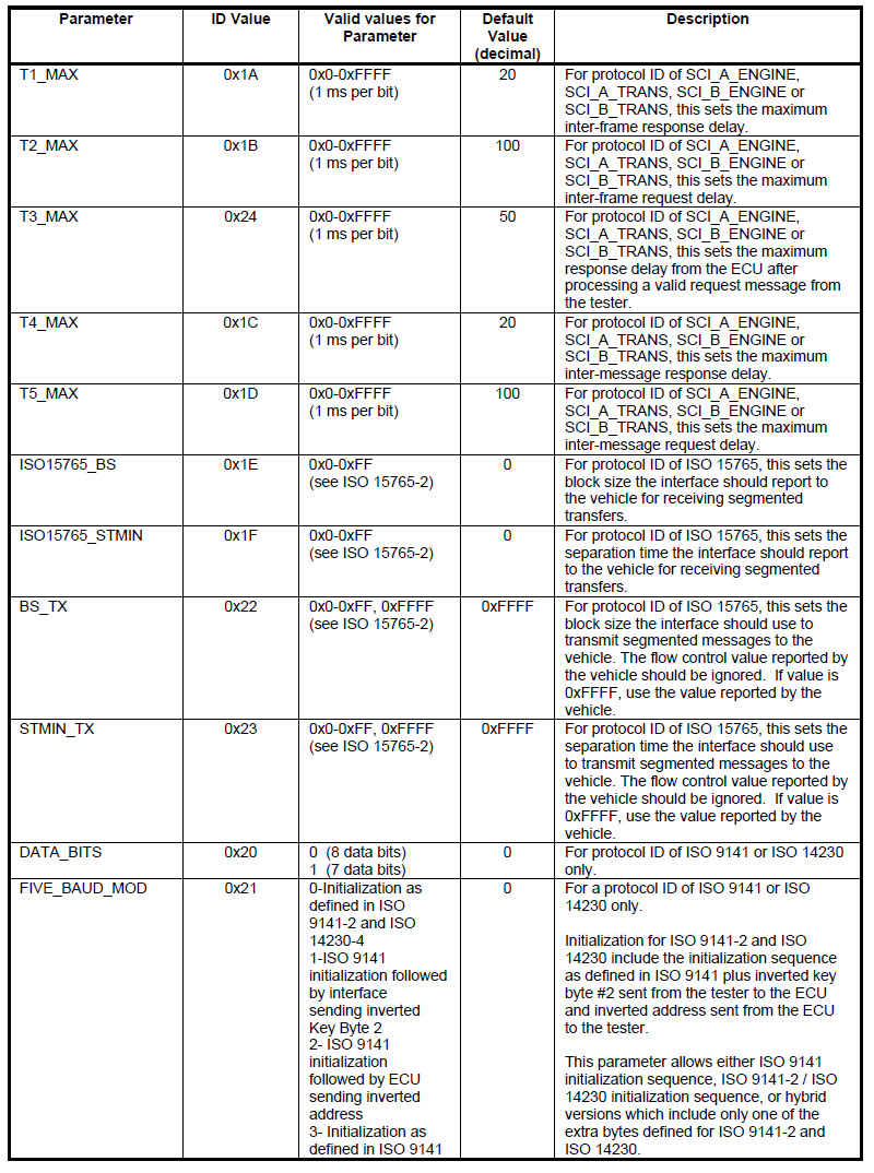
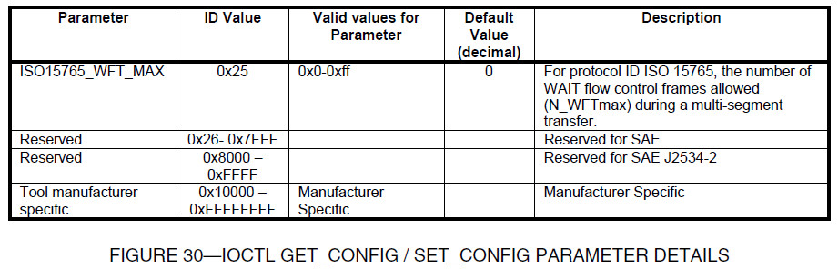
j. Support for timer values that are less than or greater than those specified in ISO 9141 (see Figure 30 in Section 7.3.2).
k. Support ability to disable automatic ISO 9141-2 / ISO 14230 checksum verification by the interface to allow vehicle manufacturer specific error detection.
l. If the ISO 9141 checksum is verified by the interface, and the checksum is incorrect, the message will be discarded.
m. Support both ISO 9141 5-baud initialization and ISO 14230 fast initialization.
n. Interface shall not adjust timer parameters based on keyword values.
6.5.2 ISO 14230-4 (KWP2000)
The ISO 14230 protocol has the same specifications as the ISO 9141 protocol as outlined in the previous section.
In addition, the following specifications clarify and, if in conflict with ISO 14230, override any related specifications in ISO 14230:
a. The pass-thru interface will not automatically handle tester present messages. The application needs to handle tester present messages when required.
b. The pass-thru interface will not perform any special handling for the $78 response code.
Any message received with a $78 response code will be passed from the interface to the application.
The application is required to handle any special timing requirements based on receipt of this response code, including stopping any periodic messages.
6.5.3 SAE J1850 41.6 KBPS PWM (PULSE WIDTH MODULATION)
The following additional features of SAE J1850 must be supported by the pass-thru device:
a. Capable of 41.6 kbps and high speed mode of 83.3 kbps.
b. Recommend Ford approved SAE J1850PWM (SCP) physical layer
6.5.4 SAE J1850 10.4 KBPS VPW (VARIABLE PULSE WIDTH)
The following additional features of SAE J1850 must be supported by the pass-thru device:
a. Capable of 10.4 kbps and high speed mode of 41.6 kbps
b. 4128 byte block transfer
c. Return to normal speed after a break indication
6.5.5 CAN
The following features of ISO 11898 (CAN) must be supported by the pass-thru device:
a. 125, 250, and 500 kbps
b. 11 and 29 bit identifiers
c. Support for 80% ± 2% and 68.5% ± 2% bit sample point
d. Allow raw CAN messages. This protocol can be used to handle any custom CAN messaging protocol, including custom flow control mechanisms.
6.5.6 ISO 15765-4 (CAN)
The following features of ISO 15765-4 must be supported by the pass-thru device:
a. 125, 250, and 500 kbps
b. 11 and 29 bit identifiers
c. Support for 80% ± 2% bit sample point
d. To maintain acceptable programming times, the transport layer flow control function, as defined in ISO 15765-2, must be incorporated in the pass-thru device (see Appendix A).
If the application does not use the ISO 15765-2 transport layer flow control functionality, the CAN protocol will allow for any custom transport layer.
e. Receive a multi-frame message with an ISO15765_BS of 0 and an ISO15765_STMIN of 0, as defined in ISO 15765-2.
f. No single frame or multi-frame messages can be received without matching a flow control filter.
No multi-frame messages can be transmitted without matching a flow control filter.
g. Periodic messages will not be suspended during transmission or reception of a multi-frame segmented message.
6.5.7 SAE J2610 DAIMLERCHRYSLER SCI
Reference the SAE J2610 Information Report for a description of the SCI protocol.
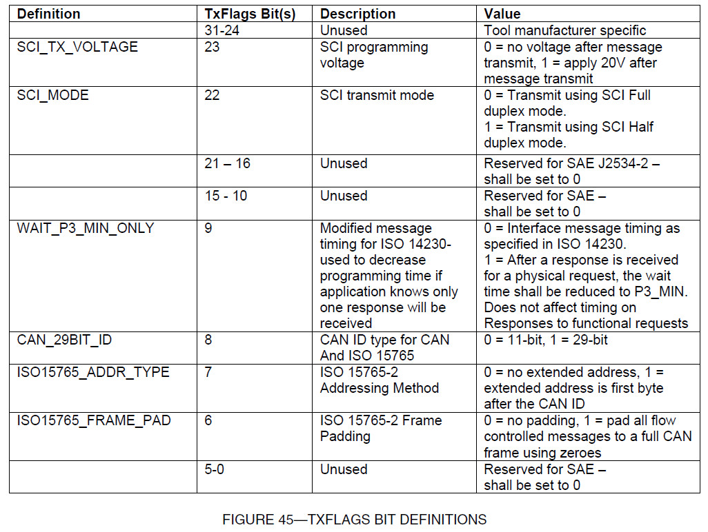
When in the half-duplex mode (when SCI_MODE of TxFlags is set to {1} Half-Duplex), every data byte sent is expected to be "echoed" by the controller.
The next data byte shall not be sent until the echo byte has been received and verified.
If the echoed byte received doesn't match the transmitted byte, or if after a period of T1 no response was received, the transmission will be terminated.
Matching echoed bytes will not be placed in the receive message queue.
What is an API?
An API (Application Programming Interface) is a 'rendezvous point' between two pieces of software.
For example, any Windows application (such as MS Word and Photoshop) can print to any printer.
How is this possible? The application and the printer driver communicate via an API. Even though each printer has different hardware,
all printer drivers 'look the same' to Windows applications.
You are free pick any printer based on your preferences (color, size, durability, cost, speed) without worrying about software incompatibilities.
In a similar vein, the J2534 API makes all "car communications" hardware look the same.
The Software
The EPA is forcing car manufacturers to release software that updates the firmware on their cars.
The application must run on Windows and use the J2534 API to talk to the car.
Anyone can buy this software, even individual car enthusiasts.
The software must be sold 'for a reasonable price', which will probably be a few hundred dollars.
The Hardware
A J2534 device plugs into a cars' OBD connector on one side, and a computer on the other side.
These devices are not made by car manufacturers, but by any company that sees an opportunity.
Under the hood, the device must speak a myriad of different vehicle protocols (ISO9141, J1850VPW/PWM, CAN, etc.)
used by the different manufacturers. Each protocol has different voltage and timing requirements,
so this is no trivial task. Fortunately, each device comes with a software driver that implements the J2534 API.
Since the driver invisibly handles communication to the device, application software
writers don't have to worry about the connection details or low-level car protocols.
http://www.drewtech.com/support/J2534/errorcodes.html
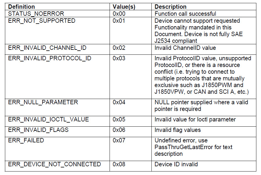
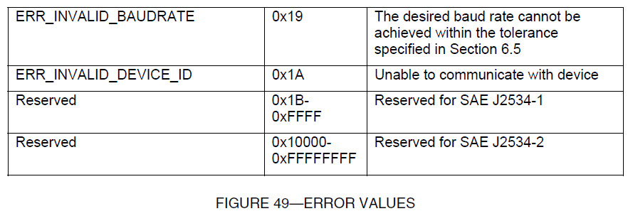
All the error codes returned by J2534 API are listed below:
| Value | Name | Description |
|---|---|---|
| 0x00 | STATUS_NOERROR | Function completed successfully. |
| 0x01 | ERR_NOT_SUPPORTED | Function option is not supported. |
| 0x02 | ERR_INVALID_CHANNEL_ID | Channel Identifier or handle is not recognized. |
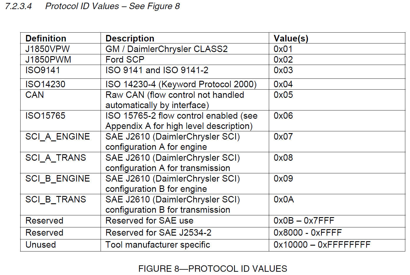
| 0x03 | ERR_INVALID_PROTOCOL_ID | Protocol Identifier is not recognized. |
| 0x04 | ERR_NULL_PARAMETER | NULL pointer presented as a function parameter, NULL is an invalid address. |
| 0x05 | ERR_INVALID_IOCTL_VALUE | Ioctl GET_CONFIG/SET_CONFIG parameter value is not recognized. |
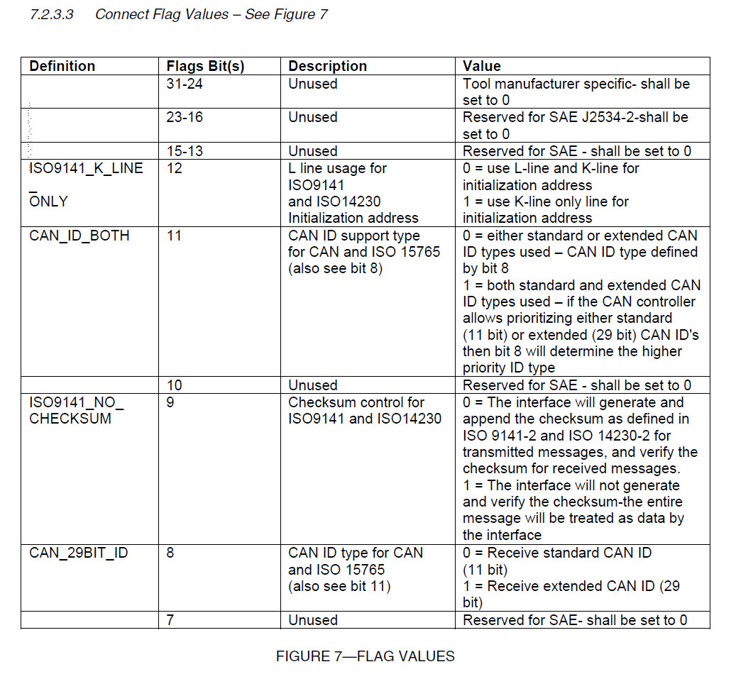
| 0x06 | ERR_INVALID_FLAGS | Flags bit field(s) contain(s) an invalid value. |
| 0x07 | ERR_FAILED | Unspecified error, use PassThruGetLastError for obtaining error text string. |
| 0x08 | ERR_DEVICE_NOT_CONNECTED | PassThru device is not connected to the PC. |
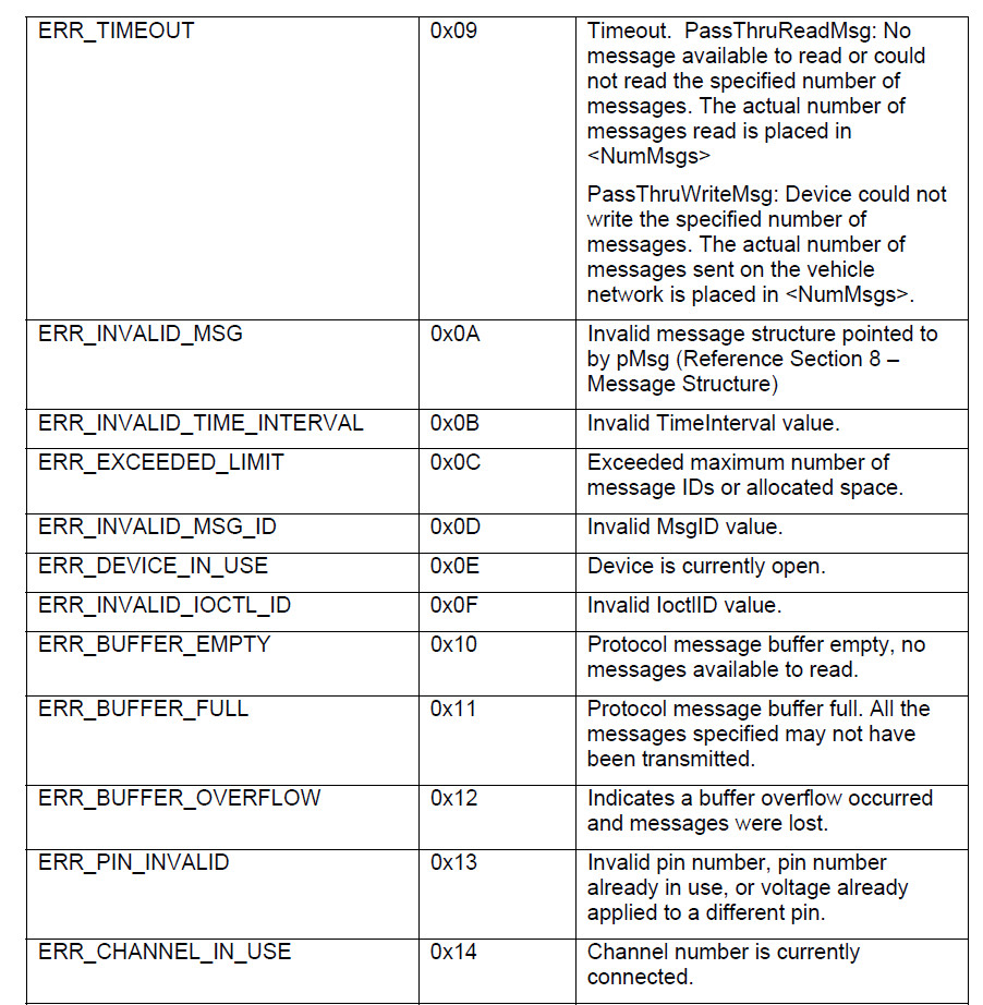
| 0x09 | ERR_TIMEOUT | Timeout violation. PassThru device is unable to read specified number of messages from the vehicle network. The actual number of messages returned is in NumMsgs. |
| 0x0A | ERR_INVALID_MSG | Message contained a min/max length, ExtraData support or J1850PWM specific source address conflict violation. |
| 0x0B | ERR_INVALID_TIME_INTERVAL | The time interval value is outside the specified range. |
| 0x0C | ERR_EXCEEDED_LIMIT | The limit (ten) of filter/periodic messages has been exceeded for the protocol associated the communications channel. |
| 0x0D | ERR_INVALID_MSG_ID | The message identifier or handle is not recognized. |
| 0x0E | ERR_DEVICE_IN_USE | The specified PassThru device is already in use. |
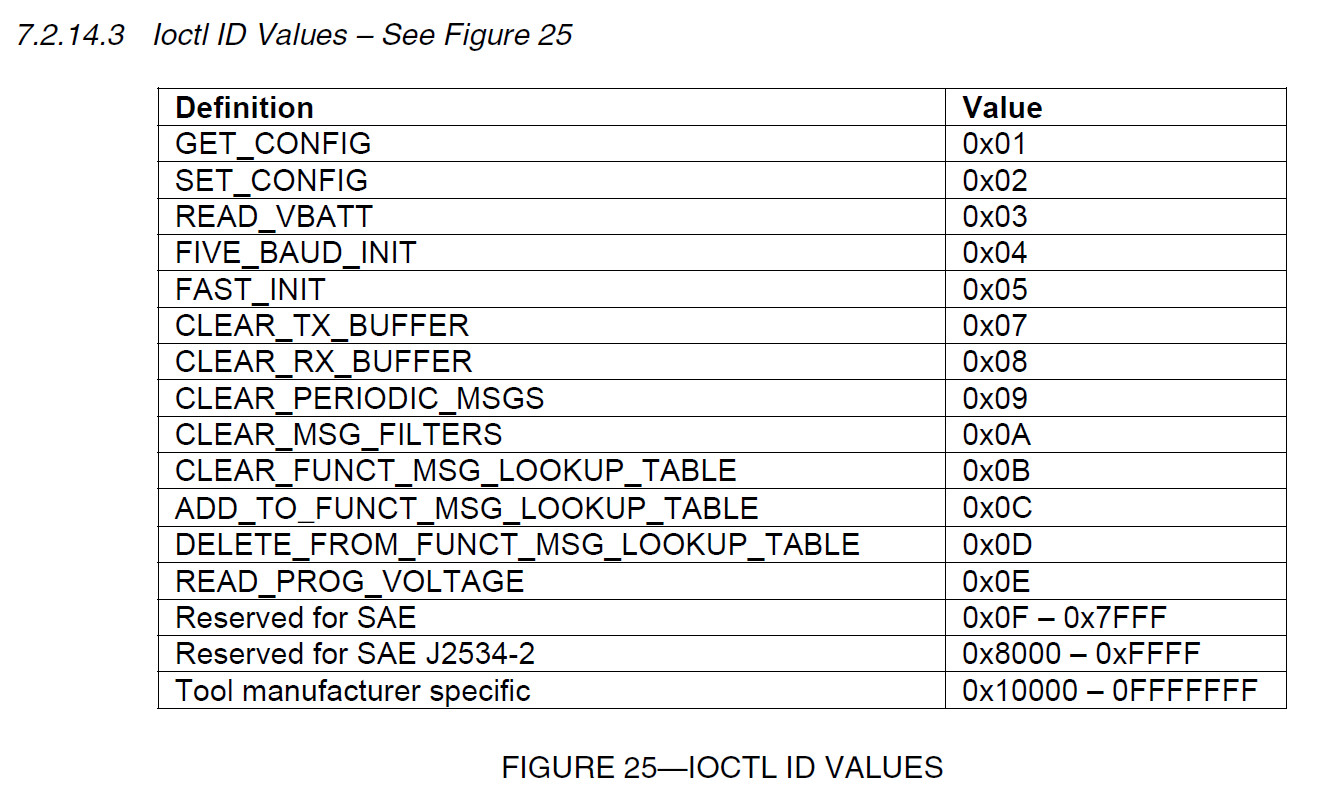
| 0x0F | ERR_INVALID_IOCTL_ID | Ioctl identifier is not recognized. |
| 0x10 | ERR_BUFFER_EMPTY | PassThru device could not read any messages from the vehicle network. |
| 0x11 | ERR_BUFFER_FULL | PassThru device could not queue any more transmit messages destined for the vehicle network. |
| 0x12 | ERR_BUFFER_OVERFLOW | PassThru device experienced a buffer overflow and receive messages were lost. |
| 0x13 | ERR_PIN_INVALID | Unknown pin number specified for the J1962 connector, or resource is already in use. |
| 0x14 | ERR_CHANNEL_IN_USE | An existing communications channel is currently using the specified network protocol. |
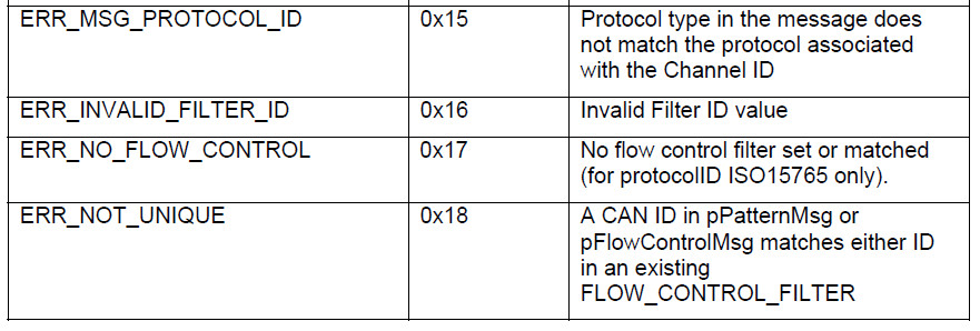
| 0x15 | ERR_MSG_PROTOCOL_ID | The specified protocol type within the message structure is different from the protocol associated with the communications channel when it was opened. |
| 0x16 | ERR_INVALID_FILTER_ID | Filter identifier is not recognized. |
| 0x17 | ERR_NO_FLOW_CONTROL | No ISO15765 flow control filter is set, or no filter matches the header of an outgoing message. |
| 0x18 | ERR_NOT_UNIQUE | An existing filter already matches this header or node identifier. |
| 0x19 | ERR_INVALID_BAUDRATE | Unable to honor requested Baud rate within required tolerances. |
| 0x1A | ERR_INVALID_DEVICE_ID | PassThru device identifier is not recognized. |
API Functions
PassThruOpen
PassThruClose
PassThruConnect
PassThruDisconnect
PassThruReadMsgs
PassThruWriteMsgs
PassThruStartPeriodicMsg
PassThruStopPeriodicMsg
PassThruStartMsgFilter
PassThruStopMsgFilter
PassThruSetProgrammingVoltage
PassThruReadVersion
PassThruGetLasError
PassThruIoctl
PassThruScanForDevices
PassThruGetNextDevice
PassThruGetDeviceContent
PassThruLogicalConnect
PassThruLogicalDisconnect
PassThruQueueMsgs
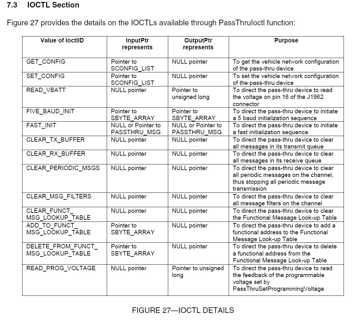
IOCTLS
GET_CONFIG
SET_CONFIG
READ_VBATT
FIVE_BAUD_INIT
FAST_INIT
CLEAR_TX_BUFFER
CLEAR_RX_BUFFER
CLEAR_PERIODIC_MSGS
CLEAR_MSG_FILTERS
CLEAR_FUNCT_MSG_LOOKUP_TABLE
DELETE_FROM_FUNCT_MSG_LOOKUP_TABLE
READ_PROG_VOLTAGE
http://www.drewtech.com/support/J2534/index.html
The following pages explain DrewTech's implementation, and should be useful to end-users who want to program with our DLL:
| Category | Name | Description |
|---|---|---|
| Setup | PassThruOpen | Initialize and connect to a CarDAQ |
| PassThruClose | Disconnect from a CarDAQ | |
| PassThruConnect | Connect to a vehicle network | |
| PassThruDisconnect | Disconnect from vehicle network | |
| PassThruIoctl | Fast init sequence (ISO 9141) | |
| PassThruIoctl | Five baud init sequence (ISO 9141) | |
| PassThruIoctl | Report configuration parameter | |
| PassThruIoctl | Set configuration parameter | |
| PassThruIoctl | Add functional address (J1850PWM) | |
| PassThruIoctl | Delete functional address (J1850PWM) | |
| PassThruIoctl | Clear functional address table (J1850PWM) | |
| Status | PassThruReadVersion | Report version information |
| PassThruGetLastError | Describe most recent error | |
| PassThruIoctl | Read vehicle battery voltage | |
| Reading | PassThruReadMsgs | Receive network message(s) |
| PassThruStartMsgFilter | Apply a network message filter | |
| PassThruStopMsgFilter | Stop a network message filter | |
| PassThruIoctl | Halt all network message filters | |
| PassThruIoctl | Clear receive buffer | |
| Writing | PassThruWriteMsgs | Transmit network message(s) |
| PassThruStartPeriodicMsg | Continuously transmit message(s) | |
| PassThruStopPeriodicMsg | Stop transmitting a message continuously | |
| PassThruIoctl | Halt all continuous messages | |
| PassThruIoctl | Clear transmit queue | |
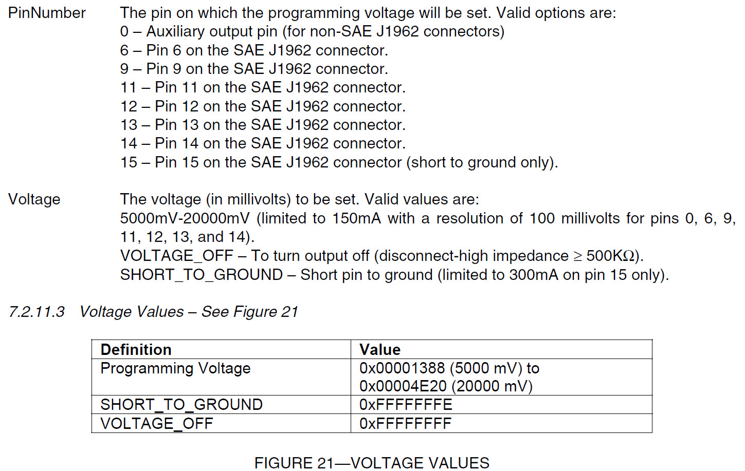
| Reflashing | PassThruSetProgrammingVoltage | Apply voltage on J1962 pin |
| PassThruIoctl | Report programming voltage | |
| Analog | PassThruIoctl | Read most recent analog sample |
| PassThruIoctl | Read stored analog sample(s) |
https://github.com/hackingvolvo/SardineCAN-Win32/tree/master/Sardine
https://github.com/hackingvolvo/SardineCAN-Win32/blob/master/Sardine/j2534_v0404.h
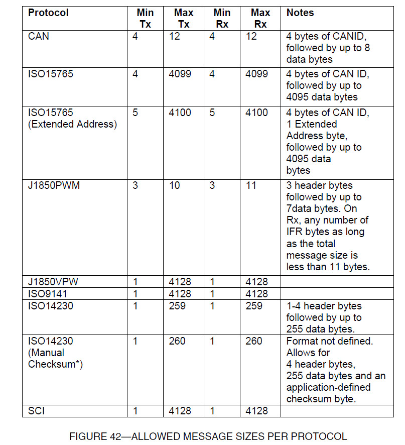
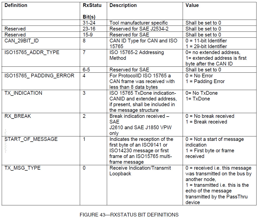
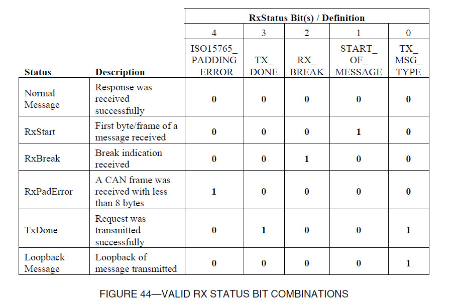
8. Message Structure
The following message structure will be used for all messages (Transmit, Receive, Filters, and Periodics)
and indications. The total message size (in bytes) is the DataSize, and includes header bytes, ID bytes,
and data bytes. For consistency, all interfaces should detect only the errors listed for each protocol in the
following sections when returning ERR_INVALID_MSG.
8.1 C / C++ Definition
typedef struct {
  unsigned long ProtocolID;
  unsigned long RxStatus;
  unsigned long TxFlags;
  unsigned long Timestamp;
  unsigned long DataSize;
  unsigned long ExtraDataIndex;
  unsigned char Data[4128];
} PASSTHRU_MSG;
SAE J2534-2
SAE J2534-1 defines a standard vehicle network interface that can be used to reprogram emissionrelated control modules.
However, there is a need to support vehicles prior to the 2004 model year as well as non-emission related control modules.
The SAE J2534-2 document meets these needs by detailing extensions to an SAE J2534-1 interface.
Together, these extensions provide the framework for a common interface to protect the software investment of the Vehicle OEMs and Scan Tool manufacturers.
Only the optional features will be described by this document. Unless otherwise noted it is expected that these features are added
to a fully compliant interface adhering to the December 2004 publication of SAE J2534-1.
Only the optional features will be described by this document. Unless otherwise noted it is expected that these features
are added to a fully compliant interface adhering to the December 2004 publication of SAE J2534-1.
Extending the protocols supported by SAE J2534-1 this document adds two new types of ProtocolIDs.
1. ProtocolIDs with the suffix ‘_PS’ for connecting to a vehicle, via the SAE J1962 connector using the technique outlined in the section titled ‘SAE J1962 Pin Selection’.
2. Generic ProtocolIDs, with the suffixes ‘_CH1’ through ‘_CH128’ for protocols that terminate at a vendor specific connector on the device. See the section titled ‘Access to Additional Channels’.
5. SAE J1962 Pin Selection
5.1 Scope of the SAE J1962 Pin Selection Optional Feature
This section identifies the pin selection mechanism for ProtocolIDs that have the ‘_PS’ suffix.
The API extensions detailed here describe the method of specifying the SAE J1962 pin(s) to which the selected protocol should be connected.
While the API allows for all combinations of protocol / pin assignments, the actual combinations implemented are vendor specific.
5.2 Pass-Thru System Requirements
5.2.1 PIN USAGE
The set of pins that can be switched is dependant on the set of optional protocols supported by the interface.
A new SET_CONFIG parameter is defined for the application to specify the pins to be switched.
5.3 Win32 Application Programming Interface
5.3.1 API FUNCTIONS – OVERVIEW
The new ProtocolIDs with ‘_PS’ suffix indicates that the protocol physical layer is not connected to the SAE J1962 pins on PassThruConnect.
A new Ioctl configuration parameter is also added, that allows connection of a physical layer to specific SAE J1962 pins.
For support of SAE J2534-1 protocols on different pins than those defined in SAE J2534-1, new ProtocolIDs are assigned to enable the pin-switching feature as defined in Figure 1:
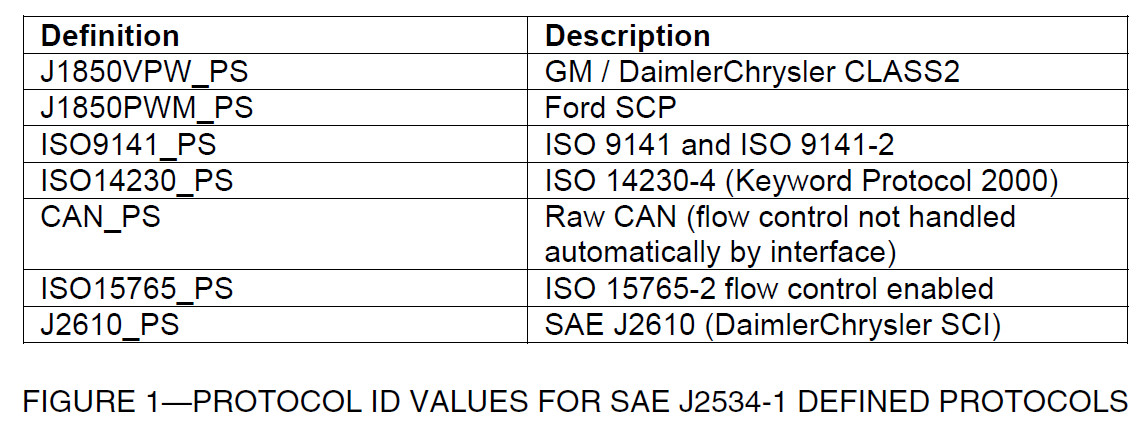
As an example, in order to utilize a CAN channel connected to Pins 3 and 11 (often used for Medium Speed CAN network), the new CAN_PS ProtocolID is used in PassThruOpen.
Note that the SAE J2610 (DaimlerChrysler SCI) protocols are consolidated into a single new ProtocolID, J2610_PS.
However the SAE J2534-1 SCI protocols shall continue to be supported as defined in SAE J2534-1.
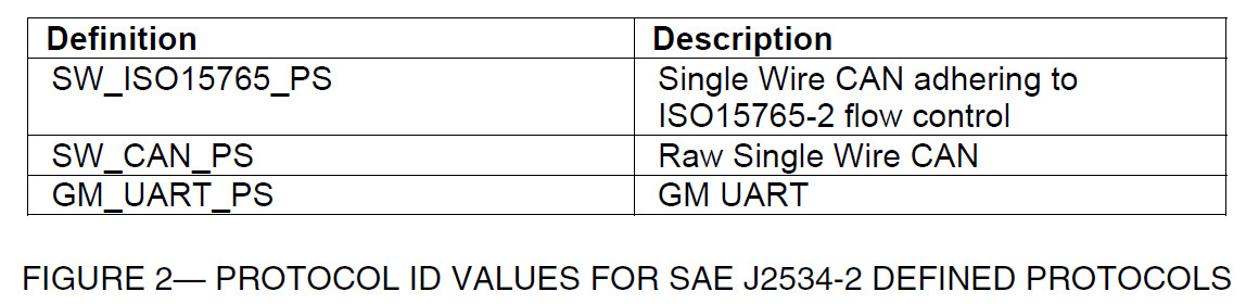
New SAE J2534-2 optional feature protocols use the ProtocolIDs defined in Figure 2:


 633
633

 被折叠的 条评论
为什么被折叠?
被折叠的 条评论
为什么被折叠?
 到【灌水乐园】发言


