#include <stdio.h>
#include <string.h>
#include <math.h>
#include "esp_log.h"
#include "freertos/FreeRTOS.h"
#include "freertos/task.h"
#include "freertos/event_groups.h"
#include "freertos/semphr.h"
#include "driver/rmt_tx.h"
#include "led_ws2812.h"
#include "driver/gpio.h"
#include "driver/adc.h"
#include "driver/i2c.h"
#include "nvs_flash.h"
#include "mqtt_client.h"
#include "simple_wifi_sta.h"
// 网络配置
#define MQTT_ADDRESS "114.55.64.216" // MQTT连接地址
#define MQTT_PORT 1863 // MQTT连接端口号
#define MQTT_CLIENT "soil_0001" // Client ID
#define MQTT_USERNAME "devname" // MQTT用户名
#define MQTT_PASSWORD "devpwd" // MQTT密码
#define MQTT_PUBLIC_TOPIC "/gws/soil_0001" // 推送消息主题
#define MQTT_SUBSCRIBE_TOPIC "/gws/soil_0001" // 订阅主题
// 定义事件组,用于通知WIFI连接成功
#define WIFI_CONNECT_BIT BIT0
static EventGroupHandle_t s_wifi_ev = NULL;
// MQTT客户端操作句柄
static esp_mqtt_client_handle_t s_mqtt_client = NULL;
// MQTT连接标志
static bool s_is_mqtt_connected = false;
// 灯带配置
#define WS2812_GPIO_NUM GPIO_NUM_45
#define WS2812_LED_NUM 6
TaskHandle_t RgbTaskHandle = NULL;
// 添加RGB任务控制事件组
static EventGroupHandle_t rgb_event_group;
#define RGB_RUN_BIT BIT0 // RGB任务运行标志位
// 雷达配置
#define LED_GPIO GPIO_NUM_16
#define LEIDA_GPIO GPIO_NUM_4
TaskHandle_t RadarTaskHandle = NULL;
// ADC配置
#define ADC_GPIO GPIO_NUM_8 // IO8对应ADC1通道7
#define ADC_CHANNEL ADC1_CHANNEL_7
TaskHandle_t AdcTaskHandle = NULL;
// I2C参数配置
#define I2C_MASTER_SCL_IO 2 // SCL引脚
#define I2C_MASTER_SDA_IO 1 // SDA引脚
#define I2C_MASTER_NUM I2C_NUM_0 // I2C控制器编号
#define I2C_MASTER_FREQ_HZ 100000 // I2C频率100kHz
#define I2C_MASTER_TX_BUF_DISABLE 0 // 禁用发送缓冲区
#define I2C_MASTER_RX_BUF_DISABLE 0 // 禁用接收缓冲区
TaskHandle_t IicTaskHandle = NULL;
// 传感器地址
#define BH1750_ADDR 0x23 // BH1750地址
#define SHT20_ADDR 0x40 // SHT20温湿度传感器地址
#define BMP280_ADDR 0x76 // BMP280 I2C地址
// BH1750寄存器定义
#define BH1750_POWER_DOWN 0x00
#define BH1750_POWER_ON 0x01
#define BH1750_RESET 0x07
#define BH1750_CONTINUOUS_HIGH_RES_MODE 0x10
// SHT20寄存器定义
#define SHT20_TRIGGER_TEMP_MEASUREMENT 0xF3
#define SHT20_TRIGGER_HUMIDITY_MEASUREMENT 0xF5
#define SHT20_SOFT_RESET 0xFE
// BMP280相关定义
#define BMP280_REG_ID 0xD0
#define BMP280_REG_RESET 0xE0
#define BMP280_REG_STATUS 0xF3
#define BMP280_REG_CTRL_MEAS 0xF4
#define BMP280_REG_CONFIG 0xF5
#define BMP280_REG_PRESS_MSB 0xF7
#define BMP280_REG_TEMP_MSB 0xFA
#define BMP280_REG_CALIB 0x88
// BMP280校准参数结构体
typedef struct {
uint16_t dig_T1;
int16_t dig_T2;
int16_t dig_T3;
uint16_t dig_P1;
int16_t dig_P2;
int16_t dig_P3;
int16_t dig_P4;
int16_t dig_P5;
int16_t dig_P6;
int16_t dig_P7;
int16_t dig_P8;
int16_t dig_P9;
} bmp280_calib_t;
// 传感器数据结构体(全局共享)
typedef struct {
float temp; // 温度(°C)
float humi; // 湿度(%)
float press; // 气压(Pa)
float lux; // 光照(lx)
float adc_voltage;// ADC电压(V)
float adc_resist; // 土壤电阻(Ω)
} sensor_data_t;
// 全局传感器数据及互斥锁
static sensor_data_t g_sensor_data = { 0 };
static SemaphoreHandle_t g_sensor_mutex;
static const char* TAG = "main";
static const char* TAG2 = "adc_radar";
static const char* TAG_ADC = "adc";
static const char* TAG_I2C = "I2C_Sensors";
/**
* mqtt连接事件处理函数
*/
static void aliot_mqtt_event_handler(void* event_handler_arg,
esp_event_base_t event_base,
int32_t event_id,
void* event_data)
{
esp_mqtt_event_handle_t event = event_data;
esp_mqtt_client_handle_t client = event->client;
switch ((esp_mqtt_event_id_t)event_id) {
case MQTT_EVENT_CONNECTED: // 连接成功
ESP_LOGI(TAG, "mqtt connected");
s_is_mqtt_connected = true;
// 连接成功后订阅主题
esp_mqtt_client_subscribe_single(s_mqtt_client, MQTT_SUBSCRIBE_TOPIC, 1);
break;
case MQTT_EVENT_DISCONNECTED: // 连接断开
ESP_LOGI(TAG, "mqtt disconnected");
s_is_mqtt_connected = false;
break;
case MQTT_EVENT_SUBSCRIBED: // 收到订阅ACK
ESP_LOGI(TAG, "mqtt subscribed ack, msg_id=%d", event->msg_id);
break;
case MQTT_EVENT_DATA: // 收到订阅消息
printf("TOPIC=%.*s\r\n", event->topic_len, event->topic);
printf("DATA=%.*s\r\n", event->data_len, event->data);
break;
case MQTT_EVENT_ERROR:
ESP_LOGI(TAG, "MQTT_EVENT_ERROR");
break;
default:
break;
}
}
/** 启动mqtt连接 */
void mqtt_start(void)
{
esp_mqtt_client_config_t mqtt_cfg = { 0 };
mqtt_cfg.broker.address.transport = MQTT_TRANSPORT_OVER_TCP;
mqtt_cfg.broker.address.hostname = MQTT_ADDRESS;
mqtt_cfg.broker.address.port = MQTT_PORT;
mqtt_cfg.credentials.client_id = MQTT_CLIENT;
mqtt_cfg.credentials.username = MQTT_USERNAME;
mqtt_cfg.credentials.authentication.password = MQTT_PASSWORD;
ESP_LOGI(TAG, "mqtt connect->clientId:%s,username:%s",
mqtt_cfg.credentials.client_id, mqtt_cfg.credentials.username);
s_mqtt_client = esp_mqtt_client_init(&mqtt_cfg);
esp_mqtt_client_register_event(s_mqtt_client, ESP_EVENT_ANY_ID,
aliot_mqtt_event_handler, s_mqtt_client);
esp_mqtt_client_start(s_mqtt_client);
}
/** wifi事件通知 */
void wifi_event_handler(WIFI_EV_e ev)
{
if (ev == WIFI_CONNECTED)
{
xEventGroupSetBits(s_wifi_ev, WIFI_CONNECT_BIT);
}
}
/** I2C主控制器初始化 */
static esp_err_t i2c_master_init(void)
{
i2c_config_t conf = {
.mode = I2C_MODE_MASTER,
.sda_io_num = I2C_MASTER_SDA_IO,
.scl_io_num = I2C_MASTER_SCL_IO,
.sda_pullup_en = GPIO_PULLUP_ENABLE,
.scl_pullup_en = GPIO_PULLUP_ENABLE,
.master.clk_speed = I2C_MASTER_FREQ_HZ,
};
ESP_ERROR_CHECK(i2c_param_config(I2C_MASTER_NUM, &conf));
return i2c_driver_install(I2C_MASTER_NUM, conf.mode,
I2C_MASTER_RX_BUF_DISABLE, I2C_MASTER_TX_BUF_DISABLE, 0);
}
/** 初始化BH1750环境光传感器 */
bool bh1750_init(void)
{
ESP_LOGI(TAG_I2C, "Initializing BH1750...");
// 软复位
i2c_cmd_handle_t cmd = i2c_cmd_link_create();
i2c_master_start(cmd);
i2c_master_write_byte(cmd, (BH1750_ADDR << 1) | I2C_MASTER_WRITE, true);
i2c_master_write_byte(cmd, BH1750_RESET, true);
i2c_master_stop(cmd);
esp_err_t ret = i2c_master_cmd_begin(I2C_MASTER_NUM, cmd, pdMS_TO_TICKS(100));
i2c_cmd_link_delete(cmd);
if (ret != ESP_OK) {
ESP_LOGE(TAG_I2C, "BH1750 reset failed: 0x%x", ret);
return false;
}
vTaskDelay(pdMS_TO_TICKS(10));
// 启动连续高分辨率模式
cmd = i2c_cmd_link_create();
i2c_master_start(cmd);
i2c_master_write_byte(cmd, (BH1750_ADDR << 1) | I2C_MASTER_WRITE, true);
i2c_master_write_byte(cmd, BH1750_CONTINUOUS_HIGH_RES_MODE, true);
i2c_master_stop(cmd);
ret = i2c_master_cmd_begin(I2C_MASTER_NUM, cmd, pdMS_TO_TICKS(100));
i2c_cmd_link_delete(cmd);
if (ret != ESP_OK) {
ESP_LOGE(TAG_I2C, "BH1750 mode set failed: 0x%x", ret);
return false;
}
ESP_LOGI(TAG_I2C, "BH1750 initialized successfully");
return true;
}
/** 读取BH1750环境光强度 */
float bh1750_read_light(void)
{
uint8_t data[2] = { 0 };
i2c_cmd_handle_t cmd = i2c_cmd_link_create();
i2c_master_start(cmd);
i2c_master_write_byte(cmd, (BH1750_ADDR << 1) | I2C_MASTER_READ, true);
i2c_master_read_byte(cmd, &data[0], I2C_MASTER_ACK);
i2c_master_read_byte(cmd, &data[1], I2C_MASTER_NACK);
i2c_master_stop(cmd);
esp_err_t ret = i2c_master_cmd_begin(I2C_MASTER_NUM, cmd, pdMS_TO_TICKS(100));
i2c_cmd_link_delete(cmd);
if (ret != ESP_OK) {
ESP_LOGE(TAG_I2C, "BH1750 read failed: 0x%x", ret);
return -1;
}
// 计算光照强度(lx)
uint16_t light = (data[0] << 8) | data[1];
return light / 1.2; // 根据数据手册计算
}
/** 初始化SHT20温湿度传感器 */
bool sht20_init(void)
{
ESP_LOGI(TAG_I2C, "Initializing SHT20...");
// 软复位
i2c_cmd_handle_t cmd = i2c_cmd_link_create();
i2c_master_start(cmd);
i2c_master_write_byte(cmd, (SHT20_ADDR << 1) | I2C_MASTER_WRITE, true);
i2c_master_write_byte(cmd, SHT20_SOFT_RESET, true);
i2c_master_stop(cmd);
esp_err_t ret = i2c_master_cmd_begin(I2C_MASTER_NUM, cmd, pdMS_TO_TICKS(100));
i2c_cmd_link_delete(cmd);
if (ret != ESP_OK) {
ESP_LOGE(TAG_I2C, "SHT20 reset failed: 0x%x", ret);
return false;
}
vTaskDelay(pdMS_TO_TICKS(15)); // 等待复位完成
ESP_LOGI(TAG_I2C, "SHT20 initialized successfully");
return true;
}
/** 读取SHT20测量值 */
static bool sht20_read_measurement(uint8_t command, float* value, bool is_temperature)
{
// 发送测量命令
i2c_cmd_handle_t cmd = i2c_cmd_link_create();
i2c_master_start(cmd);
i2c_master_write_byte(cmd, (SHT20_ADDR << 1) | I2C_MASTER_WRITE, true);
i2c_master_write_byte(cmd, command, true);
i2c_master_stop(cmd);
esp_err_t ret = i2c_master_cmd_begin(I2C_MASTER_NUM, cmd, pdMS_TO_TICKS(100));
i2c_cmd_link_delete(cmd);
if (ret != ESP_OK) {
ESP_LOGE(TAG_I2C, "SHT20 measurement trigger failed: 0x%x", ret);
return false;
}
// 等待测量完成(温度100ms,湿度40ms)
vTaskDelay(pdMS_TO_TICKS(is_temperature ? 100 : 40));
// 读取测量结果(3字节:MSB, LSB, CRC)
uint8_t data[3] = { 0 };
cmd = i2c_cmd_link_create();
i2c_master_start(cmd);
i2c_master_write_byte(cmd, (SHT20_ADDR << 1) | I2C_MASTER_READ, true);
i2c_master_read_byte(cmd, &data[0], I2C_MASTER_ACK);
i2c_master_read_byte(cmd, &data[1], I2C_MASTER_ACK);
i2c_master_read_byte(cmd, &data[2], I2C_MASTER_NACK);
i2c_master_stop(cmd);
ret = i2c_master_cmd_begin(I2C_MASTER_NUM, cmd, pdMS_TO_TICKS(100));
i2c_cmd_link_delete(cmd);
if (ret != ESP_OK) {
ESP_LOGE(TAG_I2C, "SHT20 read failed: 0x%x", ret);
return false;
}
// 提取原始值(清除状态位)
uint16_t raw_value = (data[0] << 8) | data[1];
raw_value &= 0xFFFC; // 清除最后两位状态位
// 计算实际值
if (is_temperature) {
*value = -46.85 + (175.72 * raw_value) / 65536.0;
}
else {
*value = -6.0 + (125.0 * raw_value) / 65536.0;
}
return true;
}
/** 读取SHT20温度 */
float sht20_read_temperature(void)
{
float temperature = 0.0;
if (!sht20_read_measurement(SHT20_TRIGGER_TEMP_MEASUREMENT, &temperature, true)) {
ESP_LOGE(TAG_I2C, "Failed to read SHT20 temperature");
return -1;
}
return temperature;
}
/** 读取SHT20湿度 */
float sht20_read_humidity(void)
{
float humidity = 0.0;
if (!sht20_read_measurement(SHT20_TRIGGER_HUMIDITY_MEASUREMENT, &humidity, false)) {
ESP_LOGE(TAG_I2C, "Failed to read SHT20 humidity");
return -1;
}
return humidity;
}
/** 初始化BMP280气压传感器 */
bool bmp280_init(bmp280_calib_t* calib)
{
ESP_LOGI(TAG_I2C, "Initializing BMP280...");
// 重置设备
i2c_cmd_handle_t cmd = i2c_cmd_link_create();
i2c_master_start(cmd);
i2c_master_write_byte(cmd, (BMP280_ADDR << 1) | I2C_MASTER_WRITE, true);
i2c_master_write_byte(cmd, BMP280_REG_RESET, true);
i2c_master_write_byte(cmd, 0xB6, true); // 复位值
i2c_master_stop(cmd);
esp_err_t ret = i2c_master_cmd_begin(I2C_MASTER_NUM, cmd, pdMS_TO_TICKS(100));
i2c_cmd_link_delete(cmd);
if (ret != ESP_OK) {
ESP_LOGE(TAG_I2C, "BMP280 reset failed: 0x%x", ret);
return false;
}
vTaskDelay(pdMS_TO_TICKS(10)); // 等待复位完成
// 检查设备ID
uint8_t id = 0;
cmd = i2c_cmd_link_create();
i2c_master_start(cmd);
i2c_master_write_byte(cmd, (BMP280_ADDR << 1) | I2C_MASTER_WRITE, true);
i2c_master_write_byte(cmd, BMP280_REG_ID, true);
i2c_master_start(cmd);
i2c_master_write_byte(cmd, (BMP280_ADDR << 1) | I2C_MASTER_READ, true);
i2c_master_read_byte(cmd, &id, I2C_MASTER_NACK);
i2c_master_stop(cmd);
ret = i2c_master_cmd_begin(I2C_MASTER_NUM, cmd, pdMS_TO_TICKS(100));
i2c_cmd_link_delete(cmd);
if (ret != ESP_OK || id != 0x58) { // BMP280 ID为0x58
ESP_LOGE(TAG_I2C, "BMP280 ID check failed: 0x%02X", id);
return false;
}
// 读取校准参数
uint8_t calib_data[24] = { 0 };
cmd = i2c_cmd_link_create();
i2c_master_start(cmd);
i2c_master_write_byte(cmd, (BMP280_ADDR << 1) | I2C_MASTER_WRITE, true);
i2c_master_write_byte(cmd, BMP280_REG_CALIB, true);
i2c_master_start(cmd);
i2c_master_write_byte(cmd, (BMP280_ADDR << 1) | I2C_MASTER_READ, true);
i2c_master_read(cmd, calib_data, sizeof(calib_data), I2C_MASTER_LAST_NACK);
i2c_master_stop(cmd);
ret = i2c_master_cmd_begin(I2C_MASTER_NUM, cmd, pdMS_TO_TICKS(100));
i2c_cmd_link_delete(cmd);
if (ret != ESP_OK) {
ESP_LOGE(TAG_I2C, "BMP280 calibration read failed: 0x%x", ret);
return false;
}
// 解析校准参数
calib->dig_T1 = (calib_data[1] << 8) | calib_data[0];
calib->dig_T2 = (calib_data[3] << 8) | calib_data[2];
calib->dig_T3 = (calib_data[5] << 8) | calib_data[4];
calib->dig_P1 = (calib_data[7] << 8) | calib_data[6];
calib->dig_P2 = (calib_data[9] << 8) | calib_data[8];
calib->dig_P3 = (calib_data[11] << 8) | calib_data[10];
calib->dig_P4 = (calib_data[13] << 8) | calib_data[12];
calib->dig_P5 = (calib_data[15] << 8) | calib_data[14];
calib->dig_P6 = (calib_data[17] << 8) | calib_data[16];
calib->dig_P7 = (calib_data[19] << 8) | calib_data[18];
calib->dig_P8 = (calib_data[21] << 8) | calib_data[20];
calib->dig_P9 = (calib_data[23] << 8) | calib_data[22];
// 配置传感器 (温度x2 + 气压x16,正常模式)
cmd = i2c_cmd_link_create();
i2c_master_start(cmd);
i2c_master_write_byte(cmd, (BMP280_ADDR << 1) | I2C_MASTER_WRITE, true);
i2c_master_write_byte(cmd, BMP280_REG_CTRL_MEAS, true);
i2c_master_write_byte(cmd, 0b10110111, true); // 温度x2,气压x16,正常模式
i2c_master_stop(cmd);
ret = i2c_master_cmd_begin(I2C_MASTER_NUM, cmd, pdMS_TO_TICKS(100));
i2c_cmd_link_delete(cmd);
if (ret != ESP_OK) {
ESP_LOGE(TAG_I2C, "BMP280 config failed: 0x%x", ret);
return false;
}
ESP_LOGI(TAG_I2C, "BMP280 initialized successfully");
return true;
}
/** 读取BMP280温度和气压原始值 */
static bool bmp280_read_raw(int32_t* temp_raw, int32_t* press_raw)
{
uint8_t data[6] = { 0 };
i2c_cmd_handle_t cmd = i2c_cmd_link_create();
i2c_master_start(cmd);
i2c_master_write_byte(cmd, (BMP280_ADDR << 1) | I2C_MASTER_WRITE, true);
i2c_master_write_byte(cmd, BMP280_REG_PRESS_MSB, true);
i2c_master_start(cmd);
i2c_master_write_byte(cmd, (BMP280_ADDR << 1) | I2C_MASTER_READ, true);
i2c_master_read(cmd, data, sizeof(data), I2C_MASTER_LAST_NACK);
i2c_master_stop(cmd);
esp_err_t ret = i2c_master_cmd_begin(I2C_MASTER_NUM, cmd, pdMS_TO_TICKS(100));
i2c_cmd_link_delete(cmd);
if (ret != ESP_OK) {
ESP_LOGE(TAG_I2C, "BMP280 read raw failed: 0x%x", ret);
return false;
}
*press_raw = (data[0] << 12) | (data[1] << 4) | (data[2] >> 4);
*temp_raw = (data[3] << 12) | (data[4] << 4) | (data[5] >> 4);
return true;
}
/** 计算实际温度和气压值 */
static void bmp280_compensate(const bmp280_calib_t* calib,
int32_t adc_T, int32_t adc_P,
float* temperature, float* pressure)
{
// 补偿温度
int32_t var1, var2, T;
var1 = (((double)adc_T) / 16384.0 - ((double)calib->dig_T1) / 1024.0) * ((double)calib->dig_T2);
var2 = (((double)adc_T) / 131072.0 - ((double)calib->dig_T1) / 8192.0) * (((double)adc_T) / 131072.0 - ((double)calib->dig_T1) / 8192.0) * ((double)calib->dig_T3);
int32_t t_fine = (int32_t)(var1 + var2);
T = (var1 + var2) / 5120.0; // 温度补偿值
*temperature = (float)T * 100; // 单位:°C
// 补偿气压
int64_t p, var3, var4;
var1 = ((double)t_fine / 2.0) - 64000.0;
var2 = var1 * var1 * (double)calib->dig_P6 / 32768.0;
var2 = var2 + ((var1 * (double)calib->dig_P5) * 2.0);
var2 = (var2 / 4.0) + (((double)calib->dig_P4) * 65536.0);
var1 = (((double)calib->dig_P3) * var1 * var1 / 524288.0 + ((double)calib->dig_P2) * var1) / 524288.0;
var1 = (1.0 + var1 / 32768.0) * ((double)calib->dig_P1);
p = 1048576 - (double)adc_P;
p = (p - (var2 / 4096.0)) * 6250.0 / var1;
var1 = ((double)calib->dig_P9) * p * p / 2147483648.0;
var2 = p * ((double)calib->dig_P8) / 32768.0;
p = p + (var1 + var2 + ((double)calib->dig_P7)) / 16.0;
*pressure = (float)p; // 单位:Pa
}
/** 读取BMP280温度和气压 */
bool bmp280_read(const bmp280_calib_t* calib, float* temperature, float* pressure)
{
int32_t temp_raw, press_raw;
if (!bmp280_read_raw(&temp_raw, &press_raw)) {
return false;
}
bmp280_compensate(calib, temp_raw, press_raw, temperature, pressure);
*temperature /= 100.0; // 转换为°C
return true;
}
/** I2C传感器任务(处理BH1750、SHT20和BMP280) */
void task_i2c_sensors(void* pvParameters)
{
// 初始化I2C
ESP_ERROR_CHECK(i2c_master_init());
// 初始化传感器
bool bh1750_initialized = bh1750_init();
bool sht20_initialized = sht20_init();
bmp280_calib_t bmp280_calib;
bool bmp280_initialized = bmp280_init(&bmp280_calib);
vTaskDelay(pdMS_TO_TICKS(150)); // 等待传感器初始化完成
while (1) {
// 读取传感器数据
float temp = -1, humi = -1, press = -1, lux = -1;
float bmp_temp = -1;
if (sht20_initialized) {
temp = sht20_read_temperature();
humi = sht20_read_humidity();
}
if (bmp280_initialized) {
if (bmp280_read(&bmp280_calib, &bmp_temp, &press) && temp < 0) {
temp = bmp_temp; // 若SHT20温度读取失败,使用BMP280温度
}
}
if (bh1750_initialized) {
lux = bh1750_read_light();
}
// 打印传感器数据
ESP_LOGI(TAG_I2C, "Temp: %.2f°C, Humi: %.2f%%, Press: %.2fPa, Lux: %.2flx, bmp280_temp: %.2f°C",
temp, humi, press, lux, bmp_temp);
// 更新全局传感器数据(加锁保护)
if (xSemaphoreTake(g_sensor_mutex, pdMS_TO_TICKS(100)) == pdTRUE) {
g_sensor_data.temp = temp;
g_sensor_data.humi = humi;
g_sensor_data.press = press;
g_sensor_data.lux = lux;
xSemaphoreGive(g_sensor_mutex);
}
// 读取间隔
vTaskDelay(pdMS_TO_TICKS(1500));
}
}
/** 全局亮度控制变量 */
float global_brightness = 0.2f; // 默认亮度为50%
/**
* 设置全局亮度
* @param brightness 亮度值 (0.0-1.0)
*/
void set_global_brightness(float brightness) {
// 限制亮度范围
if (brightness < 0.0f) brightness = 0.0f;
if (brightness > 1.0f) brightness = 1.0f;
global_brightness = brightness;
ESP_LOGI(TAG, "Brightness set to: %.2f", global_brightness);
}
/**
* HSV转RGB颜色空间并调整亮度
* @param h 色相 (0.0-360.0)
* @param s 饱和度 (0.0-1.0)
* @param v 明度 (0.0-1.0)
* @param brightness 亮度调整因子 (0.0-1.0)
* @param r 输出红色值 (0-255)
* @param g 输出绿色值 (0-255)
* @param b 输出蓝色值 (0-255)
*/
void hsv_to_rgb(float h, float s, float v, float brightness, uint8_t *r, uint8_t *g, uint8_t *b) {
int i;
float f, p, q, t;
// 应用亮度调整(使用非线性曲线增强暗部细节)
v *= brightness * brightness; // 平方曲线使暗部更细腻
if (s == 0) {
// 无饱和度(灰色)
*r = *g = *b = (uint8_t)(v * 255);
return;
}
h /= 60.0f; // 转换为0-6范围
i = (int)floor(h) % 6;
f = h - floor(h); // 小数部分
p = v * (1 - s);
q = v * (1 - s * f);
t = v * (1 - s * (1 - f));
// 使用更精确的浮点数计算和舍入
switch (i) {
case 0: *r = (uint8_t)(v*255.0f + 0.5f); *g = (uint8_t)(t*255.0f + 0.5f); *b = (uint8_t)(p*255.0f + 0.5f); break;
case 1: *r = (uint8_t)(q*255.0f + 0.5f); *g = (uint8_t)(v*255.0f + 0.5f); *b = (uint8_t)(p*255.0f + 0.5f); break;
case 2: *r = (uint8_t)(p*255.0f + 0.5f); *g = (uint8_t)(v*255.0f + 0.5f); *b = (uint8_t)(t*255.0f + 0.5f); break;
case 3: *r = (uint8_t)(p*255.0f + 0.5f); *g = (uint8_t)(q*255.0f + 0.5f); *b = (uint8_t)(v*255.0f + 0.5f); break;
case 4: *r = (uint8_t)(t*255.0f + 0.5f); *g = (uint8_t)(p*255.0f + 0.5f); *b = (uint8_t)(v*255.0f + 0.5f); break;
default: *r = (uint8_t)(v*255.0f + 0.5f); *g = (uint8_t)(p*255.0f + 0.5f); *b = (uint8_t)(q*255.0f + 0.5f); break;
}
}
/** RGB任务(平滑波浪彩虹效果) */
void task_rgb(void* pvParameters) {
gpio_reset_pin(WS2812_GPIO_NUM);
ws2812_strip_handle_t ws2812_handle = NULL;
ws2812_init(WS2812_GPIO_NUM, WS2812_LED_NUM, &ws2812_handle);
// 初始化熄灭所有LED
for (int index = 0; index < WS2812_LED_NUM; index++) {
ws2812_write(ws2812_handle, index, 0, 0, 0);
}
// 色相偏移量(控制彩虹波浪移动) - 使用浮点数提高精度
float hue_offset = 0.0f;
// 波浪速度控制(数值越小速度越快)
const float wave_speed = 0.5f;
// 每个LED的色相间隔(减小步长使颜色过渡更平滑)
const float hue_step = 8.0f;
// 帧率控制(减少延迟提高帧率)
const TickType_t frame_delay = pdMS_TO_TICKS(30);
ESP_LOGI(TAG, "RGB task initialized with smooth rainbow wave effect");
while (1) {
// 等待RGB运行标志
xEventGroupWaitBits(rgb_event_group,
RGB_RUN_BIT,
pdFALSE, // 不自动清除位
pdTRUE, // 等待位被设置
portMAX_DELAY);
ESP_LOGI(TAG, "Smooth rainbow wave effect started");
// 持续运行彩虹效果,直到标志位被清除
while ((xEventGroupGetBits(rgb_event_group) & RGB_RUN_BIT) != 0) {
// 为每个LED设置颜色
for (int index = 0; index < WS2812_LED_NUM; index++) {
// 使用浮点数计算色相,避免整数截断
float hue = fmodf(hue_offset + index * hue_step, 360.0f);
uint8_t r, g, b;
// 转换HSV到RGB,使用全局亮度控制
hsv_to_rgb(hue, 1.0f, 0.9f, global_brightness, &r, &g, &b);
// 设置LED颜色
ws2812_write(ws2812_handle, index, r, g, b);
}
// 更新色相偏移(使用浮点数提高精度)
hue_offset = fmodf(hue_offset + wave_speed, 360.0f);
// 减少延迟,提高帧率,使动画更流畅
vTaskDelay(frame_delay);
}
// 标志位被清除,熄灭所有LED
for (int index = 0; index < WS2812_LED_NUM; index++) {
ws2812_write(ws2812_handle, index, 0, 0, 0);
}
ESP_LOGI(TAG, "Smooth rainbow wave effect stopped");
}
}
/** 雷达任务 */
void task_radar(void* pvParameters)
{
gpio_reset_pin(LED_GPIO);
gpio_reset_pin(LEIDA_GPIO);
gpio_set_direction(LED_GPIO, GPIO_MODE_OUTPUT);
gpio_set_level(LED_GPIO, 1); // 初始熄灭
gpio_config_t radar_cfg = {
.pin_bit_mask = (1ULL << LEIDA_GPIO),
.mode = GPIO_MODE_INPUT,
.pull_up_en = GPIO_PULLUP_DISABLE,
.pull_down_en = GPIO_PULLDOWN_DISABLE,
.intr_type = GPIO_INTR_DISABLE
};
gpio_config(&radar_cfg);
ESP_LOGI(TAG2, "Radar task started");
static TickType_t rgb_start_tick = 0;
const TickType_t rgb_duration = pdMS_TO_TICKS(50000); // 50秒
while (1)
{
bool detected = gpio_get_level(LEIDA_GPIO);
gpio_set_level(LED_GPIO, !detected); // 检测到物体时点亮LED
if (detected) {
// 设置RGB运行标志
if ((xEventGroupGetBits(rgb_event_group) & RGB_RUN_BIT) == 0) {
xEventGroupSetBits(rgb_event_group, RGB_RUN_BIT);
ESP_LOGI(TAG2, "RGB activated by radar");
}
rgb_start_tick = xTaskGetTickCount(); // 更新启动时间
}
// 超时检查:50秒无检测则关闭RGB
if ((xEventGroupGetBits(rgb_event_group) & RGB_RUN_BIT) &&
(xTaskGetTickCount() - rgb_start_tick > rgb_duration)) {
xEventGroupClearBits(rgb_event_group, RGB_RUN_BIT);
ESP_LOGI(TAG2, "RGB deactivated by timeout");
}
vTaskDelay(pdMS_TO_TICKS(10));
}
}
/** ADC任务(土壤传感器) */
void task_adc(void* pvParameters) {
// 配置ADC
adc1_config_width(ADC_WIDTH_BIT_12);
adc1_config_channel_atten(ADC_CHANNEL, ADC_ATTEN_DB_11);
const float vref = 3.3f; // 参考电压
const float adc_max = 4095.0f; // 12位ADC最大值
while (1) {
int adc_value = adc1_get_raw(ADC_CHANNEL);
float voltage = adc_value * vref / adc_max;
float I_value = voltage / 1000.0f; // 电流计算
float V_value = 3.3f - voltage; // 土壤两侧电压
float R_value = (I_value > 0) ? (V_value / I_value) : -1; // 电阻计算
ESP_LOGI(TAG_ADC, "ADC: %d, Voltage: %.2fV, Resist: %.2fΩ",
adc_value, voltage, R_value);
// 更新全局ADC数据
if (xSemaphoreTake(g_sensor_mutex, pdMS_TO_TICKS(100)) == pdTRUE) {
g_sensor_data.adc_voltage = voltage;
g_sensor_data.adc_resist = R_value;
xSemaphoreGive(g_sensor_mutex);
}
vTaskDelay(pdMS_TO_TICKS(1500));
}
}
/** MQTT发送任务 */
static void task_wifi_mqtt(void* pvParameters)
{
// 初始化NVS
esp_err_t ret = nvs_flash_init();
if (ret == ESP_ERR_NVS_NO_FREE_PAGES || ret == ESP_ERR_NVS_NEW_VERSION_FOUND) {
ESP_ERROR_CHECK(nvs_flash_erase());
ESP_ERROR_CHECK(nvs_flash_init());
}
s_wifi_ev = xEventGroupCreate();
EventBits_t ev = 0;
// 初始化WIFI
wifi_sta_init(wifi_event_handler);
// 等待WIFI连接成功
ev = xEventGroupWaitBits(s_wifi_ev, WIFI_CONNECT_BIT, pdTRUE, pdFALSE, portMAX_DELAY);
if (ev & WIFI_CONNECT_BIT) {
mqtt_start();
}
static char mqtt_json[512];
sensor_data_t temp_data; // 临时存储数据
while (1)
{
// 每5秒发送一次数据
if (s_is_mqtt_connected) {
// 读取全局传感器数据(加锁保护)
if (xSemaphoreTake(g_sensor_mutex, pdMS_TO_TICKS(100)) == pdTRUE) {
temp_data = g_sensor_data;
xSemaphoreGive(g_sensor_mutex);
}
// 构建JSON格式数据
snprintf(mqtt_json, sizeof(mqtt_json),
"{\"opt\":\"dev_sta\",\"val\":{"
"\"temp\":%.2f,"
"\"humi\":%.2f,"
"\"press\":%.2f,"
"\"light\":%.2f,"
"\"adc_voltage\":%.2f,"
"\"adc_resist\":%.2f"
"}}",
temp_data.temp,
temp_data.humi,
temp_data.press,
temp_data.lux,
temp_data.adc_voltage,
temp_data.adc_resist);
// 发送MQTT消息
int msg_id = esp_mqtt_client_publish(s_mqtt_client,
MQTT_PUBLIC_TOPIC,
mqtt_json,
strlen(mqtt_json),
1, // QoS=1
0); // 不保留
ESP_LOGI(TAG, "MQTT published: %s (msg_id=%d)", mqtt_json, msg_id);
}
vTaskDelay(pdMS_TO_TICKS(3000)); // 2.5秒发送一次
}
}
void app_main(void)
{
// 初始化互斥锁保护传感器数据
g_sensor_mutex = xSemaphoreCreateMutex();
configASSERT(g_sensor_mutex);
// 初始化RGB控制事件组
rgb_event_group = xEventGroupCreate();
// 启动各任务
xTaskCreate(task_adc, "adc_task", 4096, NULL, 8, &AdcTaskHandle);
xTaskCreate(task_i2c_sensors, "i2c_sensors_task", 8192, NULL, 10, &IicTaskHandle);
xTaskCreate(task_rgb, "rgb_task", 4096, NULL, 9, &RgbTaskHandle);
xTaskCreate(task_radar, "radar_task", 4096, NULL, 9, &RadarTaskHandle);
// 启动WIFI和MQTT任务
xTaskCreate(task_wifi_mqtt, "wifi_mqtt_task", 8192, NULL, 10, NULL);
}在此基础上增加蓝牙配网功能


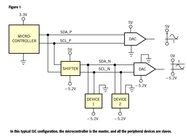
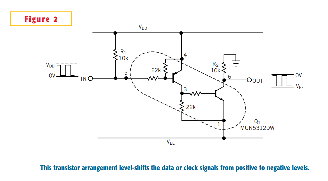
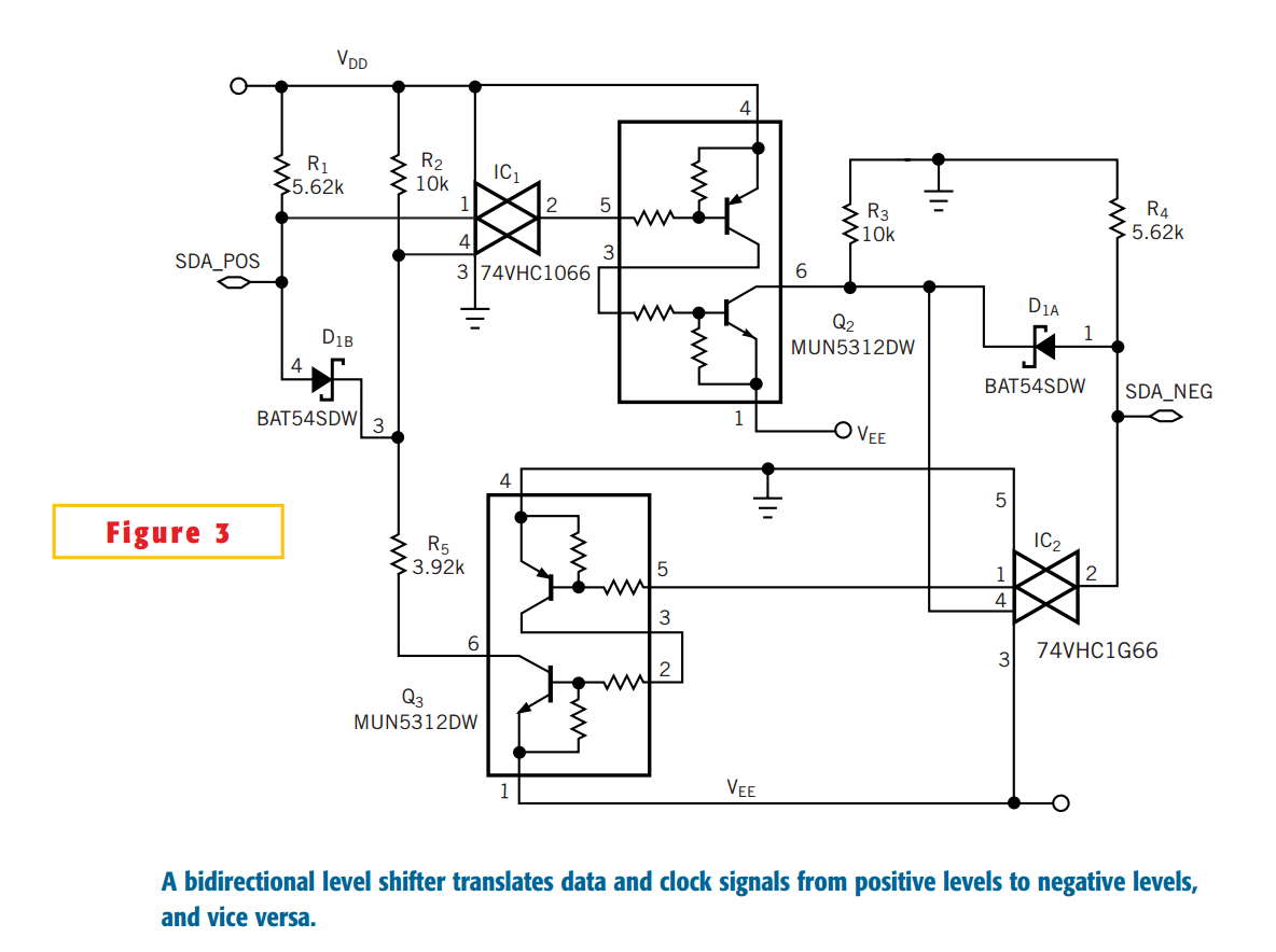
 本文详细介绍了如何在多供电系统中将5V逻辑电路存储的数字信息转换为负电压参考的模拟信号。通过采用负参考ADC转换和级转换电路,避免了传统方法引入的误差和组件数量增加的问题。


 2631
2631

 被折叠的 条评论
为什么被折叠?
被折叠的 条评论
为什么被折叠?
 到【灌水乐园】发言


