


 本文详细介绍了使用OpenGL进行图形渲染的基本原理和技术,包括顶点输入、顶点着色器、片段着色器及如何设置顶点属性等内容。
By learning OpenGL, you've decided that you want to do all of the hard work yourself. That inevitably means that you'll be thrown in the deep, but once you understand the essentials, you'll see that doing things the hard way doesn't have to be so difficult after all. To top that all, the exercises at the end of this chapter will show you the sheer amount of control you have over the rendering process by doing things the modern way!
The graphics pipeline covers all of the steps that follow each other up on processing the input data to get to the final output image. I'll explain these steps with help of the following illustration.

It all begins with the vertices, these are the points that shapes like triangles will later be contructed from. Each of these points is stored with certain attributes and it's up to you to decide what kind of attributes you want to store. Commonly used attributes are 3D position in the world and texture coordinates.
The vertex shader is a small program running on your graphics card that processes every one of these input vertices individually. This is where the perspective transformation takes place, which projects vertices with a 3D world position onto your 2D screen! It also passes important attributes like color and texture coordinates further down the pipeline.
After the input vertices have been transformed, the graphics card will form triangles, lines or points out of them. These shapes are called primitives because they form the basis of more complex shapes. There are some additional drawing modes to choose from, like triangle strips and line strips. These reduce the amount of vertices you need to pass if you want to create objects where each next primitive is connected to the last one, like a continuous line consisting of several segments.
The following step, the geometry shader, is completely optional and was only recently introduced. Unlike the vertex shader, the geometry shader can output more data than comes in. It takes the primitives from the shape assembly stage as input and can either pass a primitive through down to the rest of the pipeline, modify it first, completely discard it or even replace it with other primitive(s). Since the communication between the GPU and the rest of the PC is relatively slow, this stage can help you reduce the amount of data that needs to be transfered. With a voxel game for example, you could pass vertices as point vertices, along with an attribute for their world position, color and material and the actual cubes can be produced in the geometry shader with a point as input!
After the final list of shapes is composed and converted to screen coordinates, the rasterizer turns the visible parts of the shapes into pixel-sized fragments. The vertex attributes coming from the vertex shader or geometry shader are interpolated and passed as input to the fragment shader for each fragment. As you can see in the image, the colors are smoothly interpolated over the fragments that make up the triangle, even though only 3 points were specified.
The fragment shader processes each individual fragment along with its interpolated attributes and should output the final color. This is usually done by sampling from a texture using the interpolated texture coordinate vertex attributes or simply outputting a color. In more advanced scenarios, there could also be calculations related to lighting and shadowing and special effects in this program. The shader also has the ability to discard certain fragments, which means that a shape will be see-through there.
Finally, the end result is composed from all these shape fragments by blending them together and performing depth and stencil testing. All you need to know about these last two right now, is that they allow you to use additional rules to throw away certain fragments and let others pass. For example, if one triangle is obscured by another triangle, the fragment of the closer triangle should end up on the screen.
Now that you know how your graphics card turns an array of vertices into an image on the screen, let's get to work!
Vertex input
The first thing you have to decide on is what data the graphics card is going to need to draw your scene correctly. As mentioned above, this data comes in the form of vertex attributes. You're free to come up with any kind of attribute you want, but it all inevitably begins with the world position. Whether you're doing 2D graphics or 3D graphics, this is the attribute that will determine where the objects and shapes end up on your screen in the end.
Device coordinates
When your vertices have been processed by the pipeline outlined above, their coordinates will have been transformed into device coordinates. Device X and Y coordinates are mapped to the screen between -1 and 1.
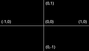
Just like a graph, the center has coordinates
(0,0)and the y axis is positive above the center. This seems unnatural because graphics applications usually have(0,0)in the top-left corner and(width,height)in the bottom-right corner, but it's an excellent way to simplify 3D calculations and to stay resolution independent.
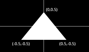
The triangle above consists of 3 vertices positioned at (0,0.5), (0.5,-0.5) and (-0.5,-0.5) in clockwise order. It is clear that the only variation between the vertices here is the position, so that's the only attribute we need. Since we're passing the device coordinates directly, an X and Y coordinate suffices for the position.
OpenGL expects you to send all of your vertices in a single array, which may be confusing at first. To understand the format of this array, let's see what it would look like for our triangle.
float vertices[] = {
     0.0f,  0.5f, // Vertex 1 (X, Y)
     0.5f, -0.5f, // Vertex 2 (X, Y)
    -0.5f, -0.5f  // Vertex 3 (X, Y)
};
As you can see, this array should simply be a list of all vertices with their attributes packed together. The order in which the attributes appear doesn't matter, as long as it's the same for each vertex. The order of the vertices doesn't have to be sequential (i.e. the order in which shapes are formed), but this requires us to provide extra data in the form of an element buffer. This will be discussed at the end of this chapter as it would just complicate things for now.
The next step is to upload this vertex data to the graphics card. This is important because the memory on your graphics card is much faster and you won't have to send the data again every time your scene needs to be rendered (about 60 times per second).
This is done by creating a Vertex Buffer Object (VBO):
GLuint vbo;
glGenBuffers(1, &vbo); // Generate 1 buffer
The memory is managed by OpenGL, so instead of a pointer you get a positive number as a reference to it. GLuint is simply a cross-platform substitute for unsigned int, just like GLint is one for int. You will need this number to make the VBO active and to destroy it when you're done with it.
To upload the actual data to it you first have to make it the active object by calling glBindBuffer:
glBindBuffer(GL_ARRAY_BUFFER, vbo);
As hinted by the GL_ARRAY_BUFFER enum value there are other types of buffers, but they are not important right now. This statement makes the VBO we just created the active array buffer. Now that it's active we can copy the vertex data to it.
glBufferData(GL_ARRAY_BUFFER, sizeof(vertices), vertices, GL_STATIC_DRAW);
Notice that this function doesn't refer to the id of our VBO, but instead to the active array buffer. The second parameter specifies the size in bytes. The final parameter is very important and its value depends on the usage of the vertex data. I'll outline the ones related to drawing here:
GL_STATIC_DRAW: The vertex data will be uploaded once and drawn many times (e.g. the world).GL_DYNAMIC_DRAW: The vertex data will be changed from time to time, but drawn many times more than that.GL_STREAM_DRAW: The vertex data will change almost every time it's drawn (e.g. user interface).
This usage value will determine in what kind of memory the data is stored on your graphics card for the highest effiency. For example, VBOs with GL_STREAM_DRAW as type may store their data in memory that allows faster writing in favour of slightly slower drawing.
The vertices with their attributes have been copied to the graphics card now, but they're not quite ready to be used yet. Remember that we can make up any kind of attribute we want and in any order, so now comes the moment where you have to explain to the graphics card how to handle these attributes. This is where you'll see how flexible modern OpenGL really is.
Shaders
As discussed earlier, there are three shader stages your vertex data will pass through. Each shader stage has a strictly defined purpose and in older versions of OpenGL, you could only slightly tweak what happened and how it happened. With modern OpenGL, it's up to us to instruct the graphics card what to do with the data. This is why it's possible to decide per application what attributes each vertex should have. You'll have to implement both the vertex and fragment shader to get something on the screen, the geometry shader is optional and is discussed later.
Shaders are written in a C-style language called GLSL (OpenGL Shading Language). OpenGL will compile your program from source at runtime and copy it to the graphics card. Each version of OpenGL has its own version of the shader language with availability of a certain feature set and we will be using GLSL 1.50. This version number may seem a bit off when we're using OpenGL 3.2, but that's because shaders were only introduced in OpenGL 2.0 as GLSL 1.10. Starting from OpenGL 3.3, this problem was solved and the GLSL version is the same as the OpenGL version.
Vertex shader
The vertex shader is a program on the graphics card that processes each vertex and its attributes as they appear in the vertex array. Its duty is to output the final vertex position in device coordinates and to output any data the fragment shader requires. That's why the 3D transformation should take place here. The fragment shader depends on attributes like the color and texture coordinates, which will usually be passed from input to output without any calculations.
Remember that our vertex position is already specified as device coordinates and no other attributes exist, so the vertex shader will be fairly bare bones.
#version 150

in vec2 position;

void main()
{
    gl_Position = vec4(position, 0.0, 1.0);
}
The #version preprocessor directive is used to indicate that the code that follows is GLSL 1.50 code. Next, we specify that there is only one attribute, the position. Apart from the regular C types, GLSL has built-in vector and matrix types indentified by vec* and mat* identifiers. The type of the values within these constructs is always a float. The number after vec specifies the amount of components (x, y, z, w) and the number after mat specifies the amount of rows /columns. Since the position attribute consists of only an X and Y coordinate, vec2 is perfect.
You can be quite creative when working with these vertex types. In the example above a shortcut was used to set the first two components of the
vec4to those ofvec2. These two lines are equal:
gl_Position = vec4(position, 0.0, 1.0);
gl_Position = vec4(position.x, position.y, 0.0, 1.0);
When you're working with colors, you can also access the first three components withr,gandbinstead ofx,yandz. This makes no difference and can help with clarity.
The final position of the vertex is assigned to the special gl_Position variable, because the position is needed for primitive assembly and many other built-in processes. For these to function correctly, the last value w needs to have a value of 1.0f. Other than that, you're free to do anything you want with the attributes and we'll see how to output those when we add color to the triangle later in this chapter.
Fragment shader
The output from the vertex shader is interpolated over all the pixels on the screen covered by a primitive. These pixels are called fragments and this is what the fragment shader operates on. Just like the vertex shader it has one mandatory output, the final color of a fragment. It's up to you to write the code for computing this color from vertex colors, texture coordinates and any other data coming from the vertex shader.
Our triangle only consists of white pixels, so the fragment shader simply outputs that color every time:
#version 150

out vec4 outColor;

void main()
{
    outColor = vec4(1.0, 1.0, 1.0, 1.0);
}
You'll immediately notice that we're not using some built-in variable for outputting the color, say gl_FragColor. This is because a fragment shader can in fact output multiple colors and we'll see how to handle this when actually loading these shaders. The outColor variable uses the type vec4, because each color consists of a red, green, blue and alpha component. Colors in OpenGL are generally represented as floating point numbers between 0.0 and 1.0 instead of the common 0 and 255.
Compiling shaders
Compiling shaders is easy once you have loaded the source code (either from file or as a hardcoded string). Just like vertex buffers, it starts with creating a shader object and loading data into it.
GLuint vertexShader = glCreateShader(GL_VERTEX_SHADER);
glShaderSource(vertexShader, 1, &vertexSource, NULL);
Unlike VBOs, you can simply pass a reference to shader functions instead of making it active or anything like that. The glShaderSource function can take multiple source strings in an array, but you'll usually have your source code in one char array. The last parameter can contain an array of source code string lengths, passing NULL simply makes it stop at the null terminator.
All that's left is compiling the shader into code that can be executed by the graphics card now:
glCompileShader(vertexShader);
Be aware that if the shader fails to compile, e.g. because of a syntax error, glGetError will not report an error! See the block below for info on how to debug shaders.
Checking if a shader compiled successfully
GLint status;
glGetShaderiv(vertexShader, GL_COMPILE_STATUS, &status);
Ifstatusis equal toGL_TRUE, then your shader was compiled successfully.
Retrieving the compile log
char buffer[512];
glGetShaderInfoLog(vertexShader, 512, NULL, buffer);
This will store the first 511 bytes + null terminator of the compile log in the specified buffer. The log may also report useful warnings even when compiling was successful, so it's useful to check it out from time to time when you develop your shaders.
The fragment shader is compiled in exactly the same way:
GLuint fragmentShader = glCreateShader(GL_FRAGMENT_SHADER);
glShaderSource(fragmentShader, 1, &fragmentSource, NULL);
glCompileShader(fragmentShader);
Again, be sure to check if your shader was compiled successfully, because it will save you from a headache later on.
Combining shaders into a program
Up until now the vertex and fragment shaders have been two separate objects. While they've been programmed to work together, they aren't actually connected yet. This connection is made by creating a program out of these two shaders.
GLuint shaderProgram = glCreateProgram();
glAttachShader(shaderProgram, vertexShader);
glAttachShader(shaderProgram, fragmentShader);
Since a fragment shader is allowed to write to multiple buffers, you need to explicitly specify which output is writing to which buffer. This needs to happen before linking the program. However, since this is 0 by default and there's only one output right now, the following line of code is not necessary:
glBindFragDataLocation(shaderProgram, 0, "outColor");
After attaching both the fragment and vertex shaders, the connection is made by linking the program. It is allowed to make changes to the shaders after they've been added to a program (or multiple programs!), but the actual result will not change until a program has been linked again. It is also possible to attach multiple shaders for the same stage (e.g. fragment) if they're parts forming the whole shader together. A shader object can be deleted with glDeleteShader, but it will not actualy be removed before it has been detached from all programs with glDetachShader.
glLinkProgram(shaderProgram);
To actually start using the shaders in the program, you just have to call:
glUseProgram(shaderProgram);
Just like a vertex buffer, only one program can be active at a time.
Making the link between vertex data and attributes
Although we have our vertex data and shaders now, OpenGL still doesn't know how the attributes are formatted and ordered. You first need to retrieve a reference to the position input in the vertex shader:
GLint posAttrib = glGetAttribLocation(shaderProgram, "position");
The location is a number depending on the order of the input definitions. The first and only input position in this example will always have location 0.
With the reference to the input, you can specify how the data for that input is retrieved from the array:
glVertexAttribPointer(posAttrib, 2, GL_FLOAT, GL_FALSE, 0, 0);
The first parameter references the input. The second parameter specifies the amount of values for that input, which is the same as the number of components of the vec. The third parameter specifies the type of each component and the fourth parameter specifies whether the input values should be normalized between -1.0 and 1.0 (or 0.0 and 1.0 depending on the format) if they aren't floating point numbers.
The last two parameters are arguebly the most important here and specify how the attribute is layed out in the vertex array. The first number specifies the stride, or how much bytes are between each position attribute in the array. The value 0 means that there is no data in between. This is currently the case as the position of each vertex is immediately followed by the position of the next vertex. The last parameter specifies the offset, or how much bytes from the start of the array the attribute occurs. Since there are no other attributes, this is 0 as well.
It is important to know that this function will not just store the stride and the offset, but also the VBO that is currently bound to GL_ARRAY_BUFFER. That means that you don't have to explicitly bind the correct VBO when the actual drawing functions are called. This also implies that you can use a different VBO for each attribute.
Don't worry if you don't fully understand this yet, as we'll see how to alter this to add more attributes soon enough.
glEnableVertexAttribArray(posAttrib);
Last, but not least, the vertex attribute array needs to be enabled.
Vertex Array Objects
You can imagine that real graphics programs use many different shaders and vertex layouts to take care of a wide variety of needs and special effects. Changing the active shader program is easy enough with a call to glUseProgram, but it would be quite inconvenient if you had to set up all of the attributes again every time.
Luckily, OpenGL solves that problem with Vertex Array Objects (VAO). VAOs store all of the links between the attributes and your VBOs with raw vertex data..
A VAO is created in the same way as a VBO:
GLuint vao;
glGenVertexArrays(1, &vao);
To start using it, simply bind it:
glBindVertexArray(vao);
As soon as you've bound a certain VAO, every time you call glVertexAttribPointer, that information will be stored in that VAO. This makes switching between different vertex data and vertex formats as easy as binding a different VAO! Just remember that a VAO doesn't store any vertex data by itself, it just references the VBOs you've created and how to retrieve the attribute values from them.
Since only calls after binding a VAO stick to it, make sure that you've created and bound the VAO at the start of your program.
Drawing
Now that you've loaded the vertex data, created the shader programs and linked the data to the attributes, you're ready to draw the triangle. The VAO that was used to store the attribute information is already bound, so you don't have to worry about that. All that's left is to simply call glDrawArrays in your main loop:
glDrawArrays(GL_TRIANGLES, 0, 3);
The first parameter specifies the kind of primitive (commonly point, line or triangle), the second parameter specifies how many vertices to skip at the beginning and the last parameter specifies the amount of vertices (not primitives!) to process.
When you run your program now, you should see the following:
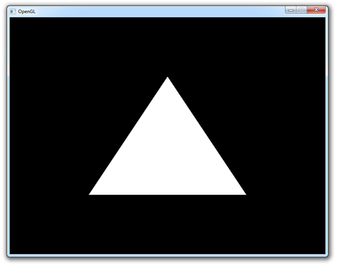
If you don't see anything, make sure that the shaders have compiled correctly, that the program has linked correctly, that the attribute array has been enabled, that the VAO has been bound before specifying the attributes, that your vertex data is correct and that glGetError returns 0. If you can't find the problem, try comparing your code to this sample.
Uniforms
Right now the white color of the triangle has been hardcoded into the shader code, but what if you wanted to change it after compiling the shader? As it turns out, vertex attributes are not the only way to pass data to shader programs. There is another way to pass data to the shaders called uniforms. These are essentially global variables, having the same value for all vertices and/or fragments. To demonstrate how to use these, let's make it possible to change the color of the triangle from the program itself.
By making the color in the fragment shader a uniform, it will end up looking like this:
#version 150

uniform vec3 triangleColor;

out vec4 outColor;

void main()
{
    outColor = vec4(triangleColor, 1.0);
}
The last component of the output color is transparency, which is not very interesting right now. If you run your program now you'll see that the triangle is black, because the value of triangleColor hasn't been set yet.
Changing the value of a uniform is just like setting vertex attributes, you first have to grab the location:
GLint uniColor = glGetUniformLocation(shaderProgram, "triangleColor");
The values of uniforms are changed with any of the glUniformXY functions, where X is the number of components and Y is the type. Common types are f (float), d (double) and i (integer).
glUniform3f(uniColor, 1.0f, 0.0f, 0.0f);
If you run your program now, you'll see that the triangle is red. To make things a little more exciting, try varying the color with the time by doing something like this in your main loop:
float time = (float)clock() / (float)CLOCKS_PER_SEC;
glUniform3f(uniColor, (sin(time * 4.0f) + 1.0f) / 2.0f, 0.0f, 0.0f);
Although this example may not be very exciting, it does demonstrate that uniforms are essential for controlling the behaviour of shaders at runtime. Vertex attributes on the other hand are ideal for describing a single vertex.
See the code if you have any trouble getting this to work.
Adding some more colors
Although uniforms have their place, color is something we'd rather like to specify per corner of the triangle! Let's add a color attribute to the vertices to accomplish this.
We'll first have to add the extra attributes to the vertex data. Transparency isn't really relevant, so we'll only add the red, green and blue components:
float vertices[] = {
     0.0f,  0.5f, 1.0f, 0.0f, 0.0f, // Vertex 1: Red
     0.5f, -0.5f, 0.0f, 1.0f, 0.0f, // Vertex 2: Green
    -0.5f, -0.5f, 0.0f, 0.0f, 1.0f  // Vertex 3: Blue
};
Then we have to change the vertex shader to take it as input and pass it to the fragment shader:
#version 150

in vec2 position;
in vec3 color;

out vec3 Color;

void main()
{
    Color = color;
    gl_Position = vec4(position, 0.0, 1.0);
}
And Color is added as input to the fragment shader:
#version 150

in vec3 Color;

out vec4 outColor;

void main()
{
    outColor = vec4(Color, 1.0);
}
Make sure that the output of the vertex shader and the input of the fragment shader have the same name, or the shaders will not be linked properly.
Now, we just need to alter the attribute pointer code a bit to accomodate for the new X, Y, R, G, B attribute order.
GLint posAttrib = glGetAttribLocation(shaderProgram, "position");
glEnableVertexAttribArray(posAttrib);
glVertexAttribPointer(posAttrib, 2, GL_FLOAT, GL_FALSE,
                       5*sizeof(float), 0);

GLint colAttrib = glGetAttribLocation(shaderProgram, "color");
glEnableVertexAttribArray(colAttrib);
glVertexAttribPointer(colAttrib, 3, GL_FLOAT, GL_FALSE,
                       5*sizeof(float), (void*)(2*sizeof(float)));
The fifth parameter is set to 5*sizeof(float) now, because each vertex consists of 5 floating point attribute values. The offset of 2*sizeof(float) for the color attribute is there because each vertex starts with 2 floating point values for the position that it has to skip over.
And we're done!
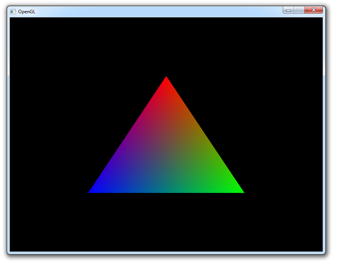
You should now have a reasonable understanding of vertex attributes and shaders. If you ran into problems, ask in the comments or have a look at the altered source code.
Element buffers
Right now, the vertices are specified in the order in which they are drawn. If you wanted to add another triangle, you would have to add 3 additional vertices to the vertex array. There is a way to control the order, which also enables you to reuse existing vertices. This can save you a lot of memory when working with real 3D models later on, because each point is usually occupied by a corner of three triangles!
An element array is filled with unsigned integers refering to vertices bound to GL_ARRAY_BUFFER. If we just want to draw them in the order they are in now, it'll look like this:
GLuint elements[] = {
    0, 1, 2
};
They are loaded into video memory through a VBO just like the vertex data:
GLuint ebo;
glGenBuffers(1, &ebo);

...

glBindBuffer(GL_ELEMENT_ARRAY_BUFFER, ebo);
glBufferData(GL_ELEMENT_ARRAY_BUFFER,
    sizeof(elements), elements, GL_STATIC_DRAW);
The only thing that differs is the target, which is GL_ELEMENT_ARRAY_BUFFER this time.
To actually make use of this buffer, you'll have to change the draw command:
glDrawElements(GL_TRIANGLES, 3, GL_UNSIGNED_INT, 0);
The first parameter is the same as with glDrawArrays, but the other ones all refer to the element buffer. The second parameter specifies the amount of indices to draw, the third parameter specifies the type of the element data and the last parameter specifies the offset. The only real difference is that you're talking about indices instead of vertices now.
To see how an element buffer can be beneficial, let's try drawing a rectangle using two triangles. We'll start by doing it without an element buffer.
float vertices[] = {
    -0.5f,  0.5f, 1.0f, 0.0f, 0.0f, // Top-left
     0.5f,  0.5f, 0.0f, 1.0f, 0.0f, // Top-right
     0.5f, -0.5f, 0.0f, 0.0f, 1.0f, // Bottom-right

     0.5f, -0.5f, 0.0f, 0.0f, 1.0f, // Bottom-right
    -0.5f, -0.5f, 1.0f, 1.0f, 1.0f, // Bottom-left
    -0.5f,  0.5f, 1.0f, 0.0f, 0.0f  // Top-left
};
By calling glDrawArrays instead of glDrawElements like before, the element buffer will simply be ignored:
glDrawArrays(GL_TRIANGLES, 0, 6);
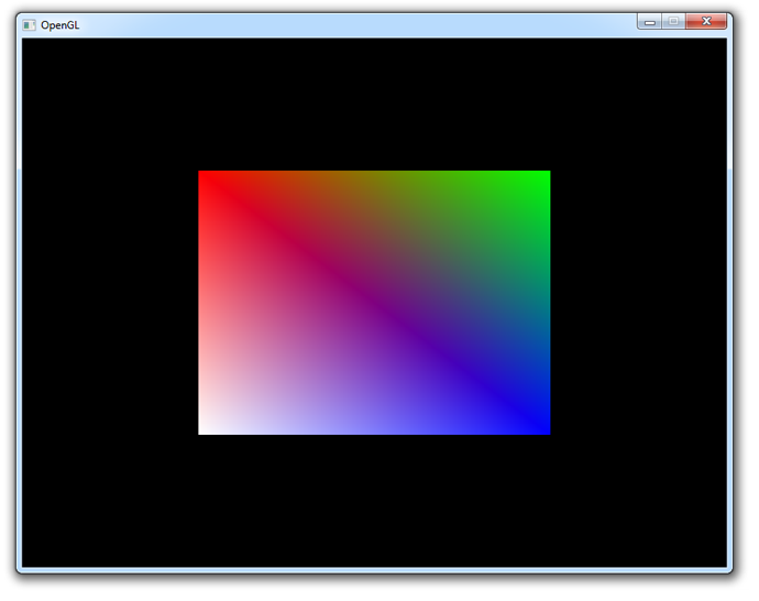
The rectangle is rendered as it should, but the repetition of vertex data is a waste of memory. Using an element buffer allows you to reuse data:
float vertices[] = {
    -0.5f,  0.5f, 1.0f, 0.0f, 0.0f, // Top-left
     0.5f,  0.5f, 0.0f, 1.0f, 0.0f, // Top-right
     0.5f, -0.5f, 0.0f, 0.0f, 1.0f, // Bottom-right
    -0.5f, -0.5f, 1.0f, 1.0f, 1.0f  // Bottom-left
};

...

GLuint elements[] = {
    0, 1, 2,
    2, 3, 0
};

...

glDrawElements(GL_TRIANGLES, 6, GL_UNSIGNED_INT, 0);
The element buffer still specifies 6 vertices to form 2 triangles like before, but now we're able to reuse vertices! This may not seem like much of a big deal at this point, but when your graphics application loads many models into the relatively small graphics memory, element buffers will be an important area of optimization.
If you run into trouble, have a look at the full source code.
This chapter has covered all of the core principles of drawing things with OpenGL and it's absolutely essential that you have a good understanding of them before continuing. Therefore I advice you to do the exercises below before diving into textures.


 249
249

 被折叠的 条评论
为什么被折叠?
被折叠的 条评论
为什么被折叠?
 到【灌水乐园】发言


