


ADS7828的配置
在ADS7828的PDF文档中有一个原理图,Ref in/Ref out 的接法如图所示。
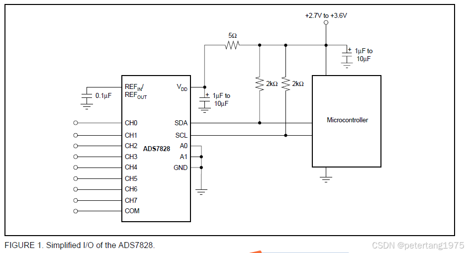 这个Ref in/Ref out 也可以接3.3V电压。
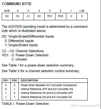
因此两种接法,在编写程序时要配合Command Byte。
如果按图1接法,则Command Byte中PD1、PD0要选择1、1,即 Internal Reference ON and Converter ON
如果Ref in/Ref out 接3.3V电压,则Command Byte中PD1、PD0要选择0、1,即 Internal Reference OFF and Converter ON。
这里不能选错,否则,可能读不到电压。
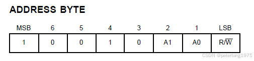
如果A1 A0,为00,则地址为0x90,取R/W=0
u16 Get_ads7828_0(u8 ch)
{
 	u8 dat = 0;
	u8 dat1 = 0;
	switch(ch)//10010100
	{
		case 0:	on_ISendByte(0x90,(0x84 | (0<<4)));				/*发送CMD 1***0111CH0  1001 0100 1000 0111*/
				break;
		case 1: on_ISendByte(0x90,(0x84 | (4<<4)));		/*发送CMD 1***0111CH1*/ // 1000 0111  0100  0000     0100 C7
				break;
		case 2: on_ISendByte(0x90,(0x84 | (1<<4)));		/*发送CMD 1***0111CH2*/  //1000 0111   0001 0000     97
				break;
		case 3: on_ISendByte(0x90,(0x84 | (5<<4)));		/*发送CMD 1***0111CH3*/
				break;
		case 4: on_ISendByte(0x90,(0x84 | (2<<4)));		/*发送CMD 1***0111CH4*/
				break;
		case 5: on_ISendByte(0x90,(0x84 | (6<<4)));		/*发送CMD 1***0111CH5*/
				break;
		case 6: on_ISendByte(0x90,(0x84 | (3<<4)));		/*发送CMD 1***0111CH6*/
				break;
		case 7: on_ISendByte(0x90,(0x84 | (7<<4)));		/*发送CMD 1***0111CH7*/
				break;
	}


	delay_us(1);
	IIC_Start();
	IIC_Send_Byte(0x91);  //1001 0101   //这个是读,r/w=1,
	IIC_Wait_Ack();

	dat = IIC_Read_Byte(1)& 0xf;		   /*dat 与返回的值类型不一致*/
  //IIC_Ack();
	dat1 = IIC_Read_Byte(0);
	//IIC_NAck();
	IIC_Stop();
	delay_us(5);
	return ((dat<<8)|dat1);
}


 1377
1377

 被折叠的 条评论
为什么被折叠?
被折叠的 条评论
为什么被折叠?
 到【灌水乐园】发言


