VGA to RGB + composite sync -converter
Designed by Tomi Engdahl
This article consists of one circuits which I have designed for connecting VGA card to other display devices than just a VGA monitor. This circuits makes it possible to connect your VGA card to fixed frequency monitors and video projectors. For some applications and system combinations some additional software is needed to get the system working.
I keep all the rights to this circuit. You can freely build this circuit for your own use but you are not allowed to use those circuit designs commercially without written permission from the designer.
VGA to RGB + Composite Sync converter
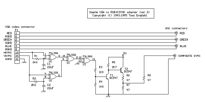
First circuit is for connecting VGA card to video projector or a monitor which accept VGA card frequencies and has RGB + Composite sync input. This circuit has been succesfully used with Electrohome Projection Systems ECP 4100 data and video projector.
This circuit is designed for converting normal VGA signals standard RGB signals and composite sync signal. The circuit is quite simple, because RGB signal ouput from VGA card is already standard 0.7Vpp to 75 ohm load.
For sync signals there is a circuit which combines horizonal and vertical sync signals to form composite sync singals. The circuit is simply based on one TTL chip with four XOR ports, two resistors and two capacitors. TTL chip ws logical choise because VGA sync signals are TTL level signals.
The sync signal combiner has a system to adjust to different sync polarities so that it always makes correct composite sync signals. VGA card uses different sync signal polarities to tell the monitor which resolution is used. This circuit adjusts to sync signal polarity changes in less than 200 milliseconds, which is faster than setting time of a normal VGA monitor in the display mode change.
Analogue composite sync signal converter
First circuit is for connecting VGA card to video projector or a monitor which accept VGA card frequencies and has RGB + Composite sync input (1 Vpp signal level, 75 ohm input impedance).

This picture is available in GIF and Postscript versions.
Note: The circuit diagram does not show the wire giving power to IC1. The +5V power is connected to pin 14 and ground is connected to pin 7.
This circuit has been succesfully used with Electrohome Projection Systems ECP 4100 video projector in many VGA and SuperVGA modes. The circuit have been also used succesfully with one old Barco video projector using my VGA to TV drivers to get the VGA card to generate suitable signal frequencies which that old video projector can handle.
Component list
C1      22 uF 10V electrolytic
C2      22 uF 10V electrolytic
R1      2.2 kohm
R2      2.2 kohm
R3      1.8 kohm
R4      1.8 kohm
R5      2.7 kohm
R6..R8  47 ohm
U1      74LS86 or 74HCT86
T1      BC 547
T2      BC 547
TTL level sync signal
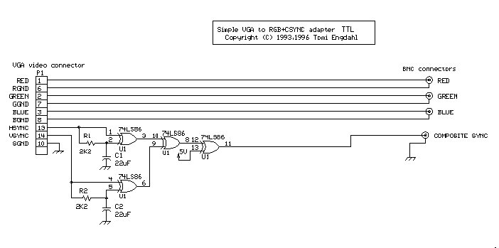
Many computer monitors have been designed to accept TTL level sync signals. If you happen to own a monitor which uses TTL level sync signals the circuit above does work with with it, because the sync signal level from that circuit is not enough for the monitor. I have designed another simpler circuit for monitors which need TTL levels.
Note: The circuit diagram does not show the wire giving power to IC1. The +5V power is connected to pin 14 and ground is connected to pin 7.
This circuit is basically the same as the first circuit. The only only difference is that the transistor driver stage have been left out from the circuit, because not so much driving capacity is needed and TTL levels signals from the IC are what is wanted. Because the 74LS86 IC directly drives the output without any further buffering, it is only suitable for driving high impedance (1 kohm or more) sync inputs.
Component list
C1      22 uF 10V electrolytic
C2      22 uF 10V electrolytic
R1      2.2 kohm
R2      2.2 kohm
U1      74LS86 or 74HCT86
Simple sync combining BOX
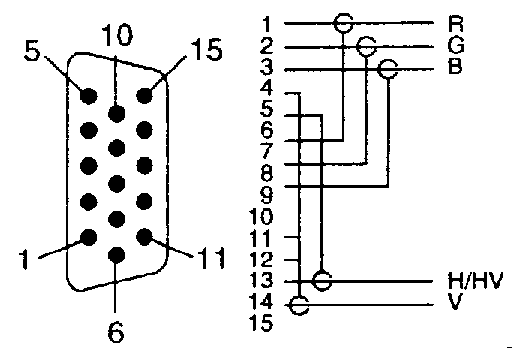
Sometimes you want to use a ready-made BNC cable made for connecting VGA card to high quality monitor. Those BNC cables have 5 BNC outputs with following functions:
Signal   Function        Color in cable
---------------------------------------
R        Red             Red
G        Green           Green
B        Blue            Blue
H/HV     Hsync(+Vsync)   Black
V        Vsync           White or Gray
Tha cables are usually built (should be built!) from high quality 75 ohm coaxial cable and 75 ohm BNC conenctors to guarantee good image quality. You can see a typical schematic of commercial VGA to BNC cable below:
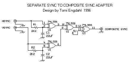
This kind of cable can be used with monitors with 5 BNC inputs. But if you unfortinately have a monitor with RGB and composite sync inputs only, that cable might not be of any use, unless your graphics card can generate composite sync signals (this is not a standard option). If you cna get composite sync directly from graphics card, then it is enough to just connect the H/HV connector to the composite sync pinput of the monitor.
If you are on unfortunate person who deos not have this kind of graphics card or your drivers don't allow using that option, then your only choice is to build a circuit which combines the separate HSYNC and VSYNC signals to composite sync. You can see this kind of circuit below.
Component list
C1      22 uF 10V electrolytic
C2      22 uF 10V electrolytic
R1      2.2 kohm
R2      2.2 kohm
U1      74LS86 or 74HCT86
Connecting VGA to Sync-on-Green monitor
Some monitors use sync-on-green syncronization instead of separate sync. In that case you can't used my circuits directly. You have to modify those circuits to add Sync-on-Green capability. Generating sync signals to screen picture component is quite easy. I have not had any need for such a circuit, so I haven't designed such option. Check this article to get the idea what to add to my circuits. For more complete explanation how to deal with sync on green monitors, check the Sync on Green FAQ.
Building the circuit
The circuit is quite simple to built if you have basic skills in building electronic circuits. The electronics of the circuits can be easily built to a small piece of veroboard so no special circuit board is necessarily needed (I used this approach in my prototype). I have designed a circuit board for myVGA to TV converter and this same PCB design (GIF picture scanned at 300x300 dots/inc resolution, also available in zipped postscript file format) and component layout can be used with this project also. Note that there are some differences in connection of the IC U1 pins in PCB compared to the schematic, but the circuit built to this PCB fuctions in the same way.
The circuit need well-stabilized power +5V power source (+/- 5%). The circuit takes less than 150 mA current, so you don't need a large power supply. If you don't have anythign suitable avalable, you can always use a small general purpose wall transformer and a small +5V voltage regulation circuit. Another option is to take the +5V power from PC using methods explained in my How to get power from PC to your circuitsdocument.
The wiring should be made carefully and 75 ohm coaxial cabling for picture signals should be used everywhere, especially if you are going to use this circuit with a high resolution monitor. Signals reclections caused by bad wiring can really mess up your picture quality. I would recommend using metal box, shielded cables and shielded connectors for circuit to keep noise and radio interference minimum.
VGA to RGBS converter component list
U1        74LS86
C1,C2     22 microfarads, 16V
R1,R2     2.2 kohm, 1/4 W
R3,R4     1.8 kohm, 1/4 W
R5        2.7 kohm, 1/4 W
R6,R7,R9  47 ohm, 1/2 W
R8        120 ohm, 1/2 W
T1,T2     BC547B
P1        15 pin SUB-D connector

Output connector:
75 ohm BNC connectors (you need 4 BNC connectors)

Wiring:
Red, Green, Blue and Composite Sync lines should be
wired using 75 ohm coaxial cable.
If you are building my TTL level output model, you can leave out R3-R8 and T1-T2 out of this list.
Getting your equipment to accept signal from PC
Many modern compter monitors are multisync monitors which accedpt easily wide selection of different refresh rates, scan frequencies and resolutions. This same applies to modern data projectors. But many older monitors (monitors not made for PC) and video projectors can't accept the signals your VGA card puts out.
If your video projection system or monitor don't accept VGA scanning frequences you have to get a suitable driver for adjusting your VGA frequencies. For normal VGA modes the horizonal sync frequency is 31250 Hz and vertical sync frequency is 60 or 72 Hz. For information about SuperVGA modes you have to consult you display card adapter technical data.
Another use for the same circuit is to connect to connect VGA card to a large old color monitor from an old workstation. If you manage to set your VGA adapter to generate suitable scanning frequecies for the monitor you have, you can use it with your VGA card. For more information how to do this, check the VGA to workstation monitor FAQ.
How to find fixed frequency monitor technical data
Befor you can start eny useful experimenting have to find out the horizonal frequency and the refresh rates your monitor needs. If you try to use the monitor with wrong frequency signals the monitor does not work properly and some monitors can be damaged if you try to use them at wrong frequency.
Your monitor user's guide technical info section is the first place to check. If that does not help try the manufacturer's website. Monitor databases like The World Wide Web Monitor Database and Apple Macintosh Monitor Database are very useful information sources for getting this information. If you can't find any technical info on the exact monitor you have you might check the information about some very similar monitor model (for example some older revision of that model) and use it as some kind starting point. If you know the computer model where the monitor was connected you can try to look at the technical specs or some FAQ of that computer (if you get to know what kind of signal that computer has sent to monitor you know that the monitor can at least show it).
How to configure Windows
Your video card drivers quite propably has options to set the the screen refresh rate. Check you graphics card manual and driver documents how to adjust those settings (this depends on graphics cards). Try to find a refresh rate and resolution which matches you monitor specifications. Typically the selections in typical drivers are quite limited and many driver's don't have any further options for user customization.
Matrox has added excellent user configurability oprtions for their Millenium and Mystique graphics card Windows 95 drivers. For more information take a look at my info page how to confire Matrox cards to TV frequencies because thet page has also lots of information how to change tha settings and this information is useful if you have to make configuration for some fixed frequency monitor you have.
Configuting Linux XFree86 for fixed frequency monitors
Linux XFree86 has excellent user configurability by editing XF86Config file which has all necessary video card parameters in it and that file can be edited with any ASCII editor. Changing those parameters in gonfiguation file properlu needs some experinece. For more information on configuring XFree86 take a look at Use your old Workstation Monitors with Linux/XFree86 and The Hitchhiker's Guide to X386/XFree86 Video Timing.
How to use old video projectors and TV studio monitors
If you happen to own an old video projector which is capable of displaying only PAL/NTSC/SECAM video picture but has RGB inputs, you might find my signal conversion circuits still useful. You can make your VGA card to generate signal which is suitable for this type of monitos or video projectors using the drivers designed for my VGA to TV circuit. Those drivers are available for standard VGA modes in DOS. Some support is also available for some cards for SuperVGA modes in DOS, Windows and Linux Xfree86.
Other related projects
I have also designed a VGA to TV adapter using this same basic circuit. With some additional software and small modifications this circuit can be used for connecting VGA card to TV equipped with SCART connector.


 本文介绍了一种用于将VGA信号转换为RGB及复合同步信号的电路设计方案,适用于连接VGA显卡到固定频率显示器或视频投影仪。该方案包括组合水平和垂直同步信号形成复合同步信号的电路,支持多种同步极性调整。


 被折叠的 条评论
为什么被折叠?


