


前言
上一篇做了一个类似ViewPager的控件,算是复习了一下自定义view的知识,也实现了比较厉害的效果。这一篇简单点,是我发现前面几篇对于onDraw函数讲的还是不多,而且又发现Paint这个类还是相当复杂的,就利用一个六边形评分控件学习一下,罗列了一下Paint的功能,简单试了试。
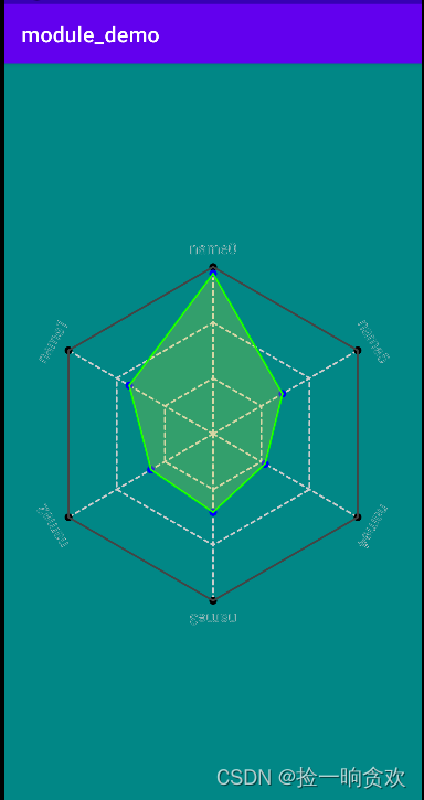
需求
需求很简单,看下面核心思想:
- 1、六个顶点连成六边形作为边界,顶点上需要有字提示数据类型
- 2、六个数据作为得分,在中心到顶点连线上,六个评分再围成六边形
- 3、边界六边形为空心,内部六边形为实心
- 4、中心和顶点用虚线连接,再内部有虚线构成参考六边形
效果图
编写代码
这里主要就是绘制了,本来还想添加缩放和旋转效果的,但是最后把代码删了,这里知识已经够多了。
import android.content.Context
import android.graphics.*
import android.util.AttributeSet
import android.view.View
import com.silencefly96.module_common.R
import kotlin.math.cos
import kotlin.math.sin


/**
 * 六边形评分view
 *
 * @author silence
 * @date 2022-10-26
 */
class HexagonRankView @JvmOverloads constructor(
    context: Context,
    attributeSet: AttributeSet? = null,
    defStyleAttr: Int = 0
): View(context, attributeSet, defStyleAttr){

    /**
     * 六个数据
     */
    @Suppress("MemberVisibilityCanBePrivate")
    val data = ArrayList<PointInfo>(6)

    // 边界六顶点颜色
    private val mOutPointColor: Int

    // 边界六边的颜色
    private val mOutLineColor: Int

    // 内部六顶点颜色
    private val mInPointColor: Int

    // 内部六顶点颜色
    private val mInLineColor: Int

    // 内部填充颜色
    private val mInFillColor: Int

    // 虚线颜色
    private val mDottedLineColor: Int

    // 字体大小
    private val mTextSize: Float

    // 画笔粗细
    private val mStrokeWidth: Float

    // 填充透明度
    private val mFillAlpha: Int

    // 半径占边框中最小值的比例
    private val mRadiusPercent: Float

    // 各个点的半径
    private val mPointRadius: Float

    // 起始相位
    private val mStartPhase: Int

    // 文字距离顶点的值
    private val mTextMargin: Float

    // 画笔
    private val mPaint: Paint

    // 中点坐标
    private var mCenterX: Int = 0
    private var mCenterY: Int = 0

    // 六边形半径
    private var mRadius: Int = 0

    init {
        // 读取XML参数
        val typedArray =
            context.obtainStyledAttributes(attributeSet, R.styleable.HexagonRankView)

        mOutPointColor = typedArray.getColor(R.styleable.HexagonRankView_outPointColor,
            Color.BLACK)

        mOutLineColor = typedArray.getColor(R.styleable.HexagonRankView_outLineColor,
            Color.DKGRAY)

        mInPointColor = typedArray.getColor(R.styleable.HexagonRankView_inPointColor,
            Color.BLUE)

        mInLineColor =typedArray.getColor(R.styleable.HexagonRankView_inLineColor,
            Color.GREEN)

        mInFillColor = typedArray.getColor(R.styleable.HexagonRankView_inFillColor,
            Color.YELLOW)

        mDottedLineColor = typedArray.getColor(R.styleable.HexagonRankView_dottedLineColor,
            Color.LTGRAY)

        mTextSize = typedArray.getDimension(R.styleable.HexagonRankView_textSize, 40f)

        mStrokeWidth = typedArray.getDimension(R.styleable.HexagonRankView_strokeWidth, 5f)

        mFillAlpha = typedArray.getInt(R.styleable.HexagonRankView_fillAlpha, 50)

        mRadiusPercent = typedArray.getFraction(R.styleable.HexagonRankView_radiusPercent,
            1, 1, 0.8f)

        mPointRadius = typedArray.getDimension(R.styleable.HexagonRankView_pointRadius, 10f)

        mStartPhase = typedArray.getInt(R.styleable.HexagonRankView_startPhase, -90)

        mTextMargin = typedArray.getDimension(R.styleable.HexagonRankView_textMargin, 50f)

        typedArray.recycle()

        // 初始化画笔
        mPaint = Paint().apply {
            // 内容参考:https://blog.youkuaiyun.com/qq_27061049/article/details/102574020
            /******* 常用方法 *******/
            // 颜色
            color = Color.BLACK

            // 粗细,设置为0时无论怎么放大 都是1像素
            strokeWidth = mStrokeWidth

            // 透明度[0, 255]
            alpha = 255

            // 带透明度画笔
            setARGB(255, 255, 255,255)

            // 抗锯齿
            flags = Paint.ANTI_ALIAS_FLAG

            // 设置填充模式,FILL、STROKE、FILL_AND_STROKE(更大一些)
            style = Paint.Style.STROKE


            /******* 线条样式 *******/
            // 线条连接处样式,BEVEL(斜角)、MITER(平斜接)、ROUND(圆角)
            strokeJoin = Paint.Join.ROUND

            // 斜接模式延长线长度限制(MITER样式下),miter = len / width = 1 / sin ( θ / 2 )
            // 默认值为4,越大角度越小,比这个角度的角度,交界地方的超长三角形会被截断移除
            strokeMiter = 4f

            // 落笔和结束时那点(point)的样式,BUTT(不添加)、ROUND(添加半圆)、SQUARE(添加矩形)
            strokeCap = Paint.Cap.ROUND

            // 设置路径效果:
            // 直线,segmentLength: 分段长度,deviation: 偏移距离
            // pathEffect = DiscretePathEffect(float segmentLength, float deviation)

            // 圆角,参数为连接处的半径
            // pathEffect = CornerPathEffect(20f)

            // 虚线,intervals:必须为偶数,用于控制显示和隐藏的长度; phase:相位
            // pathEffect = DashPathEffect(float intervals[], float phase)

            // 使用 path 绘制虚线,shapePath(构成shape的path),advance(两个shape之间距离),phase(相位)
            // 指定拐弯改变的时候 shape 的转换方式,TRANSLATE:位移、ROTATE:旋转、MORPH:变体(压缩变小)
            // pathEffect = PathDashPathEffect(shapePath, advance, phase, PathDashPathEffectStyle.TRANSLATE);

            // 设置线条随机偏移(变得乱七八糟),segmentLength: 分段长度,deviation: 偏移距离
            // pathEffect = DiscretePathEffect(float segmentLength, float deviation)

            // 两种线条模式都执行(一条线变两条线)
            // pathEffect = SumPathEffect(dashEffect, discreteEffect)

            // 线条组合模式(一条线两种模式)
            // pathEffect = ComposePathEffect(dashEffect, discreteEffect)

            /******* 着色渐变及渲染 *******/
            // 渐变
            // LinearGradient 线性渐变
            // (x0,y0)(x1,y1) 两点确定线性方向,color0、color1渐变两颜色(在两点上), 渐变模式: Shader.TileMode.MIRROR
            // shader = LinearGradient(float x0, float y0, float x1, float y1, int color0, int color1, TileMode tile)

            // 三种颜色以上模式,positions:颜色的位置(比例)
            // shader = LinearGradient(float x0, float y0, float x1, float y1, int colors[], float positions[], TileMode tile)

            // RadialGradient 径向渐变(从圆心沿极径变化)
            // x、y:中心点坐标, radius:渐变半径, color0:起始颜色, color1:结束颜色, TileMode:渐变模式
            // shader = RadialGradient(float x, float y, float radius, int color0, int color1, TileMode tile)
            // 三种颜色以上模式,positions:颜色的位置(比例)
            // shader = RadialGradient(float x, float y, float radius, int colors[], float positions[], TileMode tile)

            // SweepGradient 扫描渐变(随角度变化颜色)
            // cx、cy:圆点坐标, color0:起始颜色, color1:结束颜色
            // shader = SweepGradient(float cx, float cy, int color0, int color1)
            // 多种颜色的扫描渐变, positions:颜色的位置(比例)
            // shader = SweepGradient(float cx, float cy, int colors[], float positions[])

            // BitmapShader 位图渐变(使用图片填充)
            // bitmap 位图,TileMode 横纵坐标上的模式
            // shader = BitmapShader(Bitmap bitmap, TileMode tileX, TileMode tileY)

            // Shader.TileMode 渐变模式
            // TileMode.CLAMP 模式不平铺
            // TileMode.REPEAT 模式表示平铺
            // TileMode.MIRROR 模式也表示平铺,但是交错的位图是彼此的镜像,方向相反

            // ComposeShader 混合渐变(对上面四种渐变进行混合)
            // 混合模式 PorterDuffXfermode(PorterDuff.Mode.SRC_IN)
            // ComposeShader(Shader shaderA, Shader shaderB, Xfermode mode)
            // 位图运算(16种): PorterDuff.Mode.XO
            // ComposeShader(Shader shaderA, Shader shaderB, Mode mode)


            /******* 颜色效果处理 *******/
            // LightingColorFilter 设定基本色素(过滤颜色), mul 用来和目标像素相乘,add 用来和目标像素相加
            // colorFilter = LightingColorFilter(0x00ffff, 0x000000); //去掉红色

            // PorterDuffColorFilter 设置颜色 模式运算
            // PorterDuffColorFilter(Color.GREEN, PorterDuff.Mode.XOR); //去掉 和 绿色结合的部分

            // ColorMatrixColorFilter 色彩锐度等
            // 使用一个 ColorMatrix 来对颜色进行处理, 内部是一个 4x5 的矩阵 A, B = [R, G, B, A]-T, A x B
            //colorFilter =  ColorMatrix(new float[]{
            //    -1f, 0f, 0f, 0f, 255f,
            //    0f, -1f, 0f, 0f, 255f,
            //    0f, 0f, -1f, 0f, 255f,
            //    0f, 0f, 0f, 1f, 0f }); //去掉 和 绿色结合的部分

            // setXfermode 图片转换模式
            // “Xfermode” 其实就是“Transfer mode”, Xfermode 指的是 你要绘制的内容 和 canvas 的目标位置的内容应该怎样结合计算出最终的颜色。
            // 通俗的讲就是要你以绘制的图形作为源图像,以View中已有的内容做为目标图像,选取一个PorterDuff.Mode 作为绘制内容的颜色处理方案
            // val bitmapOne = BitmapFactory.decodeResource(resources,R.mipmap.ic_launcher_2)
            // val bitmapTwo = BitmapFactory.decodeResource(resources,R.mipmap.rect_2)

            // val xfermode = PorterDuffXfermode(PorterDuff.Mode.DST_IN); //取交集,交集样式取决于下层,颜色取决于上层
            // val saved = canvas.saveLayer(null, null, Canvas.ALL_SAVE_FLAG);
            // canvas.drawBitmap(bitmapTwo, 0, 0, paint);
            // paint.setXfermode(xfermode); // 设置 Xfermode
            // canvas.drawBitmap(bitmapOne, 0, 0, paint);
            // paint.setXfermode(null); // 用完及时清除 Xfermode
            // canvas.restoreToCount(saved)


            /******* 色彩优化 *******/
            // setDither(boolean dither) 设置图像抖动
            // 在实际的应用场景中,抖动更多的作用是在图像降低色彩深度绘制时,避免出现大片的色带与色块
            // 选择 16 位色的 ARGB_4444 或者 RGB_565 的时候,开启它才会有比较明显的效果

            // setFilterBitmap(boolean filter) 线性过滤
            // 图像在放大绘制的时候,默认使用的是最近邻插值过滤,这种算法简单,但会出现马赛克现象;
            // 而如果开启了双线性过滤,就可以让结果图像显得更加平滑


            /******* 设置阴影或者上层效果 *******/
            // setShadowLayer() 设置阴影、clearShadowLayer() 清楚阴影
            // radius 是阴影的模糊范围; dx dy 是阴影的偏移量; shadowColor 是阴影的颜色
            // setShadowLayer(float radius, float dx, float dy, int shadowColor)

            // setMaskFilter(MaskFilter filter) 绘制层上附件效果,阴影是下层
            // 模糊效果的 MaskFilter,
            // NORMAL: 内外都模糊绘制、/SOLID: 内部正常绘制,外部模糊、INNER: 内部模糊,外部不绘制、/OUTER: 内部不绘制,外部模糊
            // maskFilter = BlurMaskFilter(float radius, BlurMaskFilter.Blur style)

            // EmbossMaskFilter 浮雕效果
            // direction 是一个 3 个元素的数组,指定了光源的方向; ambient 是环境光的强度,数值范围是 0 到 1; specular 是炫光的系数; blurRadius 是应用光线的范围
            // EmbossMaskFilter(float[] direction, float ambient, float specular, float blurRadius)

            /******* 获取实际路径 *******/
            // 获取线条实际路径,当线条比较粗时,路径实际是一个封闭的矩形
            // getFillPath(Path src, Path dst)
            // 获取文本的实际路径,获取到path后通过canvas去绘制path
            // getTextPath(String text, int start, int end, float x, float y, Path path)
        }
    }

    override fun onMeasure(widthMeasureSpec: Int, heightMeasureSpec: Int) {
        super.onMeasure(widthMeasureSpec, heightMeasureSpec)

        // 自定义view要设置好默认大小
        val width = getDefaultSize(100, widthMeasureSpec)
        val height = getDefaultSize(100, heightMeasureSpec)

        // 由控件宽高获得中心点坐标
        mCenterX = width / 2
        mCenterY = height / 2

        // 半径,设置为最小宽度的80%
        mRadius = ((if (mCenterX < mCenterY) mCenterX else mCenterY) * mRadiusPercent).toInt()

        // 计算数据坐标
        calculateLocation()

        setMeasuredDimension(width, height)
    }

    private fun calculateLocation() {
        // 以中点为圆心,每隔60度绘制一个顶点
        var angle: Int
        var radians: Double

        // 循环绘制
        for (i in 0..5) {
            angle = 60 * i + mStartPhase
            radians = Math.toRadians(angle.toDouble())

            // 计算横纵坐标
            data[i].x = (mRadius * cos(radians)).toFloat() + mCenterX
            data[i].y = (mRadius * sin(radians)).toFloat() + mCenterY

            // 计算分数对应的坐标
            val scan = data[i].rank / 100f
            data[i].curX = (mRadius * scan * cos(radians)).toFloat() + mCenterX
            data[i].curY = (mRadius * scan * sin(radians)).toFloat() + mCenterY
        }
    }

    override fun onDraw(canvas: Canvas) {
        super.onDraw(canvas)

        // 辅助的虚线, 放在底层
        drawDottedLine(canvas)

        // 外面的边和顶点以及标题
        drawOuter(canvas)

        // 里面多边形
        drawInner(canvas)
    }

    // 辅助的虚线,这里将半径三等分,画三个虚线六边形
    private fun drawDottedLine(canvas: Canvas) {
        var x: Float
        var y: Float

        // 路径
        val path = Path()
        mPaint.color = mDottedLineColor
        val array = FloatArray(2)
        array[0] = 10f
        array[1] = 10f
        mPaint.pathEffect = DashPathEffect(array, 0f)

        // 两层层虚线六边形
        for (i in 1..2) {
            path.reset()

            // 循环一遍获得路径
            for (point in data) {
                // 利用两点坐标计算等距离的点
                x = (point.x - mCenterX) / 3 * i + mCenterX
                y = (point.y - mCenterY) / 3 * i + mCenterY

                if (data.indexOf(point) == 0) path.moveTo(x, y)
                path.lineTo(x, y)
            }
            // 封闭
            path.close()

            // 绘制虚线六边形
            canvas.drawPath(path, mPaint)
        }

        // 绘制连接中点和顶点的虚线
        path.reset()
        for (point in data) {
            canvas.drawLine(mCenterX.toFloat(), mCenterY.toFloat(), point.x, point.y, mPaint)
        }

        //  去除虚线效果
        mPaint.pathEffect = null
    }

    // 外面的顶点
    private fun drawOuter(canvas: Canvas) {
        // 外边路径
        val path = Path()
        path.moveTo(data[0].x, data[0].y)

        // 绘制标题,在切线方向绘制
        // 顶点在最上面时,(60 * i + mStartPhase) -> (-90) => -90 - (60 * i + mStartPhase)
        val startAngle = -90 - mStartPhase
        canvas.save()
        canvas.rotate(startAngle.toFloat(), mCenterX.toFloat(), mCenterY.toFloat())

        mPaint.textAlign = Paint.Align.CENTER
        mPaint.textSize = mTextSize
        // 绘制字体要先设置为0
        mPaint.strokeWidth = 0f
        // 要画出切线效果,移动的是画布,每次在最上面横着画就行
        val x = mCenterX.toFloat()
        val y = mCenterY - mRadius - mTextMargin

        // 循环绘制
        for (i in 0..5) {
            // 绘制标题
            canvas.drawText(data[i].name, x, getBaseline(mPaint, y), mPaint)
            // 旋转60度画下一个
            canvas.rotate(-60f, mCenterX.toFloat(), mCenterY.toFloat())
        }
        // 绘制标题结束,恢复画布
        canvas.restore()

        // 循环绘制
        mPaint.color = mOutPointColor
        mPaint.strokeWidth = mStrokeWidth
        mPaint.style = Paint.Style.FILL
        for (point in data) {
            // 绘制点
            canvas.drawCircle(point.x, point.y, mPointRadius, mPaint)
            // 也可以直接用点
            // paint.setStrokeCap(Paint.Cap.SQUARE);
            // canvas.drawPoint(x, y, paint);

            // 绘制外边
            path.lineTo(point.x, point.y)
        }

        // 封闭
        path.close()
        mPaint.color = mOutLineColor
        mPaint.style = Paint.Style.STROKE
        canvas.drawPath(path, mPaint)
    }

    private fun getBaseline(paint: Paint, tempY: Float): Float {
        //绘制字体的参数,受字体大小样式影响
        val fmi = paint.fontMetricsInt
        //top为基线到字体上边框的距离(负数),bottom为基线到字体下边框的距离(正数)
        //基线中间点的y轴计算公式,即中心点加上字体高度的一半,基线中间点x就是中心点x
        return tempY - (fmi.top + fmi.bottom) / 2f
    }

    // 里面多边形
    private fun drawInner(canvas: Canvas) {
        // 里面多边形路径
        val path = Path()
        path.moveTo(data[0].curX, data[0].curY)

        // 循环绘制
        mPaint.color = mInPointColor
        mPaint.style = Paint.Style.FILL
        for (point in data) {
            // 绘制点
            canvas.drawCircle(point.curX, point.curY, mPointRadius, mPaint)

            // 添加外边路径到path
            path.lineTo(point.curX, point.curY)
        }
        // 封闭
        path.close()

        // 绘制路径
        mPaint.color = mInLineColor
        mPaint.style = Paint.Style.STROKE
        canvas.drawPath(path, mPaint)

        // 绘制内部填充
        mPaint.color = mInFillColor
        mPaint.style = Paint.Style.FILL
        mPaint.alpha = mFillAlpha
        canvas.drawPath(path, mPaint)
        // 恢复style
        mPaint.style = Paint.Style.STROKE
    }

    data class Pair(var x: Float, var y: Float)

    // 数据类,标题、分数、外边点坐标、分数点坐标
    data class PointInfo(var name: String, var rank: Int,
                         var x: Float = 0f, var y: Float = 0f,
                         var curX: Float = 0f, var curY: Float = 0f)
}
主要问题
这里Paint相关的知识我就不详细说了,主要提下下面几点:
canvas.save()和canvas.restore()
canvas.save()和canvas.restore()这两个函数中间可以对canvas进行变化,绘制的东西会保留,比如我这旋转了很多次绘制标题,最后用canvas.restore()恢复原来的位置,就不用去计算恢复的角度,自己去旋转了。Canvas的绘制方法,有兴趣可以自己找资料看看,也就那几个。
绘制字体要先设置strokeWidth为0
这里绘制字体时会受strokeWidth影响,导致加粗很多,所以绘制前要设置下。
path的moveTo
path初始默认从(0, 0)开始,需要首先利用moveTo移到开始位置。至于Path的一些方法,有兴趣也可以自己找资料看看。我的这篇文章:安卓带步骤的手写签名(附源码),用path绘制了流畅的线条,有兴趣可以瞧瞧。


 4901
4901

 被折叠的 条评论
为什么被折叠?
被折叠的 条评论
为什么被折叠?
 到【灌水乐园】发言


