


Shape
Object->DispatcherObject->DependencyObject->Visual->UIElement->FrameworkElement->Shape
如果希望启用像素对齐,可以通过UIElement类的SnapsToDevicePixels属性设置为true。
对象以处理它们的顺序被绘制出来,注意显示关系。
Shape
| 名称 | 备注 | 权限 |
|---|---|---|
| FillProperty | 标识 Fill 依赖项属性。 此字段为只读。 | public static readonly |
| StretchProperty | 标识 Stretch 依赖项属性。 | public static readonly |
| StrokeDashArrayProperty | 标识 StrokeDashArray 依赖项属性。 | public static readonly |
| StrokeDashCapProperty | 标识 StrokeDashCap 依赖项属性。 | public static readonly |
| StrokeDashOffsetProperty | 标识 StrokeDashOffset 依赖项属性。 | public static readonly |
| StrokeEndLineCapProperty | 标识 StrokeEndLineCap 依赖项属性。 | public static readonly |
| StrokeLineJoinProperty | 标识 StrokeLineJoin 依赖项属性。 | public static readonly |
| StrokeMiterLimitProperty | 标识 StrokeMiterLimit 依赖项属性。 | public static readonly |
| StrokeProperty | 标识 Stroke 依赖项属性。 | public static readonly |
| StrokeStartLineCapProperty | 标识 StrokeStartLineCap 依赖项属性。 | public static readonly |
| StrokeThicknessProperty | 标识 StrokeThickness 依赖项属性。 | public static readonly |
| 名称 | 备注 | 权限 |
|---|---|---|
| DefiningGeometry | 获取一个值,该值表示 Geometry 的 Shape。 | get; |
| Fill | 获取或设置 Brush,它指定形状内部上色的方式。 | get; set; |
| GeometryTransform | 获取一个表示 Transform 的值,该值在绘制形状之前应用于 Shape 的几何图形。 | get; |
| RenderedGeometry | 获取一个值,该值表示 Geometry 的最终呈现的 Shape。 | get; |
| Stretch | 获取或设置 Stretch 枚举值,该值描述形状如何填充为其分配的空间。 | get; set; |
| Stroke | 获取或设置 Brush,用于指定 Shape 边框绘制的方式。 | get; set; |
| StrokeDashArray | 获取或设置 Double 值的集合,这些值指示用于勾勒形状轮廓的虚线和间隙样式。 | get; set; |
| StrokeDashCap | 获取或设置一个 PenLineCap 枚举值,该值指定如何绘制虚线的两端。 | get; set; |
| StrokeDashOffset | 获取或设置一个 Double,它指定虚线样式内虚线开始处的距离。 | get; set; |
| StrokeEndLineCap | 获取或设置描述线的末端的 Shape 的 PenLineCap 枚举值。 | get; set; |
| StrokeLineJoin | 获取或设置 PenLineJoin 枚举值,该值指定在 Shape 的顶点处使用的联接类型。 | get; set; |
| StrokeMiterLimit | 获取或设置对斜接长度与 StrokeThickness 元素的 Shape 的一半之比的限制。 | get; set; |
| StrokeStartLineCap | 获取或设置在 Stroke 开头部分描述 Shape 的 PenLineCap 枚举值。 | get; set; |
| StrokeThickness | 获取或设置 Shape 边框的宽度。 | get; set; |
| 名称 | 备注 | 权限 |
|---|---|---|
| ArrangeOverride | 通过计算形状的 Shape 和 RenderedGeometry 属性来排列 Stretch。 | protected |
| MeasureOverride | 排列之前在第一个布局处理过程中测量 Shape。 | protected |
| OnRender | 提供用于更改 Shape 元素的默认外观的方法。 | protected |
Ellipse
| 名称 | 备注 | 权限 |
|---|---|---|
| 获取在呈现之前应用于 Identity 的 Geometry 的任何 Ellipse 变换的值。 | get; | |
| 获取 Geometry 的最终呈现的 Ellipse。 | get; |
Line
| 名称 | 备注 | 权限 |
|---|---|---|
| X1Property | 标识 X1 依赖项属性。 | public static readonly |
| X2Property | 标识 X2 依赖项属性。 | public static readonly |
| Y1Property | 标识 Y1 依赖项属性。 | public static readonly |
| Y2Property | 标识 Y2 依赖项属性。 | public static readonly |
| 名称 | 备注 | 权限 |
|---|---|---|
| X1 | 获取或设置 Line 起点的 x 坐标。 | get; set; |
| X2 | 获取或设置 Line 终点的 x 坐标。 | get; set; |
| Y1 | 获取或设置 Line 起始点的 y 坐标。 | get; set; |
| Y2 | 获取或设置 Line 终结点的 y 坐标。 | get; set; |
Path
若要绘制简单形状,请使用 EllipseGeometry 、 LineGeometry 和 RectangleGeometry 对象。 若要绘制曲线、弧形或复杂形状,请使用 PathGeometry 对象。 若要创建复合几何图形,请使用 GeometryGroup 。 若要组合几何图形,请使用 CombinedGeometry 。
| 名称 | 备注 | 权限 |
|---|---|---|
| 标识 Data 依赖项属性。 | public static readonly |
| 名称 | 备注 | 权限 |
|---|---|---|
| 获取或设置用于指定所要绘制的形状的 Geometry | get; set; |
Data是Geometry,参考下文。
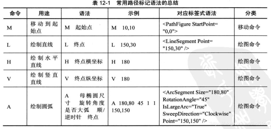
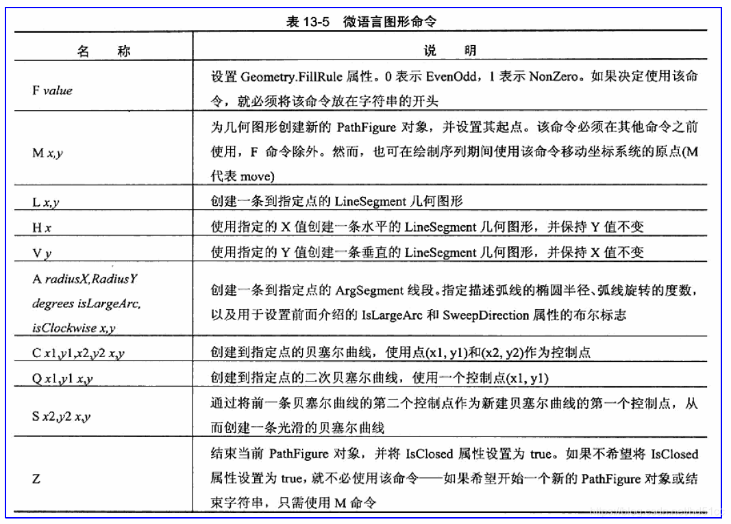
路径标记语法
Polygon
| 名称 | 备注 | 权限 |
|---|---|---|
| FillRuleProperty | 标识 FillRule 依赖项属性。 | public static readonly |
| PointsProperty | 标识 Points 依赖项属性。 | public static readonly |
| 名称 | 备注 | 权限 |
|---|---|---|
| 获取或设置指定如何确定形状内部填充的 FillRule 枚举。 | get; set; | |
| 获取或设置一个集合,它包含多边形的顶点。 | get; set; |
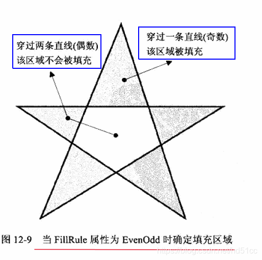
| EvenOdd | 0 | 通过从一点向任意方向绘制一条射向无穷远的射线,然后计算给定形状中与该射线相交的路径段的数目,从而确定该点是否位于填充区域的规则。 如果此数目为奇数,那么该点则在内部;如果为偶数,则该点在外部。 |
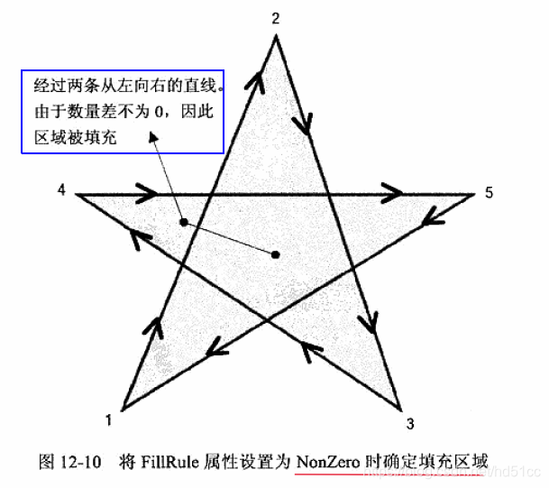
| Nonzero | 1 | 通过从一点向任意方向绘制一条射向无穷远的射线,并检查一段形状与射线相交的位置,从而确定该点是否位于路径的填充区域的规则。 从零计数开始,从左到右每次添加与射线相交的一个段,然后从右到左每次减去与射线相交的一个路径段。 在对交叉点进行计数后,如果结果为零,那么该点则位于路径外。 否则,该点则在路径内。 |
Polyline
| 名称 | 备注 | 权限 |
|---|---|---|
| 标识 FillRule 依赖项属性。 | public static readonly | |
| 标识 Points 依赖项属性。 | public static readonly |
| 名称 | 备注 | 权限 |
|---|---|---|
| 获取或设置指定如何确定形状内部填充的 FillRule 枚举。 | get; set; | |
| 获取或设置包含 Polyline 的顶点的集合。 | get; set; |
Rectangle
| 名称 | 备注 | 权限 |
|---|---|---|
| 标识 RadiusX 依赖项属性。 | public static readonly | |
| 标识 RadiusY 依赖项属性。 | public static readonly |
| 名称 | 备注 | 权限 |
|---|---|---|
| 获取适用于此 Transform 的 Rectangle。 | get; | |
| 获取或设置令矩形边角改为圆角的椭圆半径( X 轴)。 | get; set; | |
| 获取或设置令矩形边角改为圆角的椭圆半径(Y 轴)。 | get; set; | |
| 获取一个表示最终呈现的形状的 Geometry 对象。 | get; |
Brush
支持部分透明,需要设置Opacity。
静态资源System.Brushes。
Brush"绘制" 或 "填充" 带有其输出的区域。 不同的画笔具有不同的输出类型。 某些画笔使用纯色绘制区域,其他画笔使用渐变、图案、图像或绘图。 以下列表描述了不同类型的 WPF 画笔:
使用纯色绘制区域 Color 。
为方便起见, Brushes 该类提供了一组常用 SolidColorBrush 对象,例如 Blue 和 Yellow 。
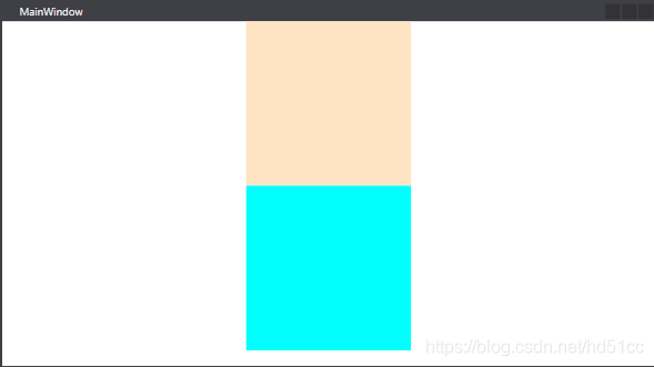
    <StackPanel>
        <Rectangle Width="200" Height="200" >
            <Rectangle.Fill>
                <SolidColorBrush Color="Bisque"/>
            </Rectangle.Fill>
        </Rectangle>
        <Rectangle Width="200" Height="200" Fill="Aqua"/>
</StackPanel>使用线性渐变绘制区域。
LinearGradientBrush使用线性渐变绘制区域。 线性渐变沿直线定义渐变。 线条的终点由 StartPoint 线性渐变的和属性定义 EndPoint 。 LinearGradientBrush画笔 GradientStops 沿这一线绘制其。
默认的线性渐变是对角。 默认情况下, StartPoint 线性渐变的是 (0,0) ,要绘制的区域的左上角,其 EndPoint 为 (1,1) ,即绘制区域的右下角。 生成的渐变中的颜色沿对角路径内插。

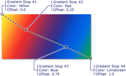
        <Rectangle Width="300" Height="180" >
            <Rectangle.Fill>
                <LinearGradientBrush StartPoint="0,0" EndPoint="1,1">
                    <GradientStop Color="Yellow" Offset="0.0"/>
                    <GradientStop Color="Red" Offset="0.25"/>
                    <GradientStop Color="Blue" Offset="0.75"/>
                    <GradientStop Color="LimeGreen" Offset="1"/>
                </LinearGradientBrush>
            </Rectangle.Fill>
</Rectangle>使用径向渐变绘制区域。
在 RadialGradientBrush 编程模型中类似于 LinearGradientBrush 。 但是,线性渐变有一个开始点和终点来定义渐变向量,而径向渐变具有一个圆圈和一个焦点,用于定义渐变行为。 圆圈定义渐变的终点。 换句话说,在1.0 的渐变停止点定义圆的周长的颜色。 焦点定义渐变的中心。 位于0.0 的渐变停止点定义焦点处的颜色。
下图显示了用径向渐变填充的矩形。 从白色到灰色的径向渐变。 外圆圈表示渐变圆,而红点表示焦点。 此渐变将其 SpreadMethod 设置为 Pad 。
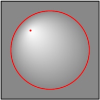
突出显示了焦点的径向渐变
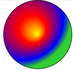
        <Ellipse Width="300" Height="300"  StrokeThickness="2" Stroke="Black">
            <Ellipse.Fill>
                <RadialGradientBrush RadiusX="0.8" RadiusY="0.8" Center="0.2,0.2">
                    <GradientStop Color="Yellow" Offset="0"/>
                    <GradientStop Color="Red" Offset="0.25"/>
                    <GradientStop Color="Blue" Offset="0.75"/>
                    <GradientStop Color="LimeGreen" Offset="1"/>
                </RadialGradientBrush>
            </Ellipse.Fill>
</Ellipse>使用由对象) 表示 (图像绘制区域 ImageSource 。
ImageBrush是的一种类型 TileBrush ,它将其内容定义为图像,由其属性指定 ImageSource 。 您可以控制图像的拉伸、对齐和平铺方式,从而生成模式和其他效果。 以下图像显示了可通过实现的一些效果 ImageBrush 。
System.windows.media.imagebrush> 可以绘制形状、控件、文本等

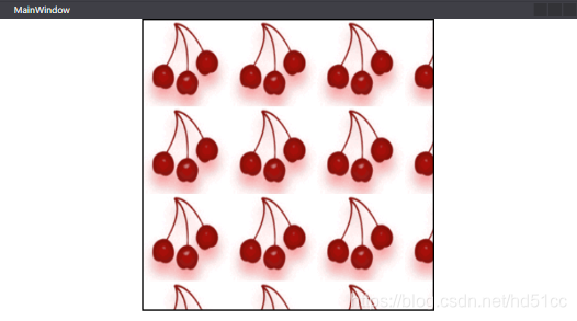
<Rectangle Height="400" Width="400" StrokeThickness="2" Stroke="Black">
<Rectangle.Fill>
<ImageBrush ImageSource=".\Img\Cherries.png" TileMode="Tile" Viewport="0,0,0.3,0.3"/>
</Rectangle.Fill>
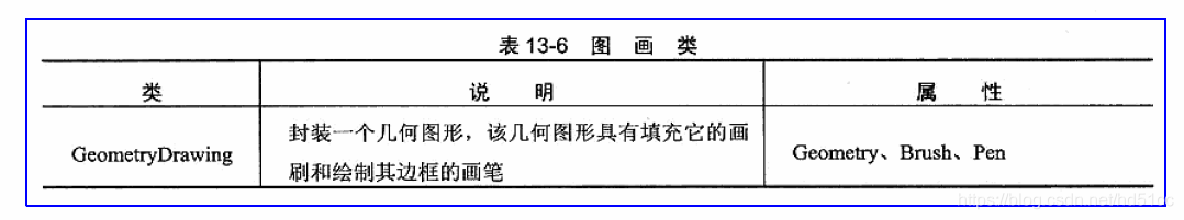
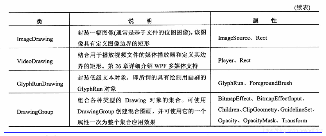
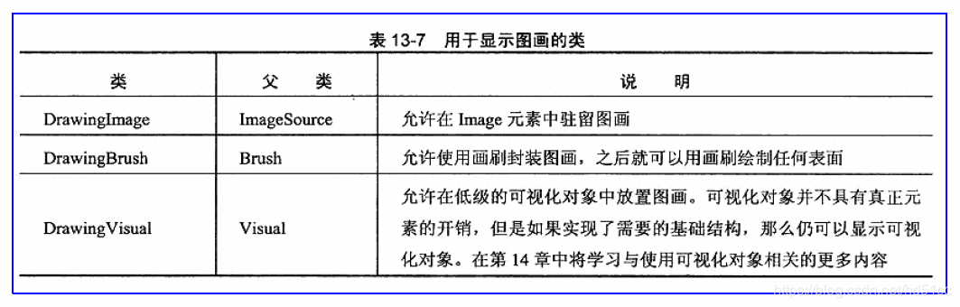
</Rectangle>使用绘制一个区域 Drawing 。 绘图可能包括矢量对象和位图对象。
DrawingBrush使用对象绘制区域 Drawing 。 Drawing对象描述可见内容,如形状、位图、视频或文本行。 不同类型的图形描述不同类型的内容。 下面是不同类型图形对象的列表。
- GeometryDrawing –绘制形状。
- ImageDrawing –绘制图像。
- GlyphRunDrawing –绘制文本。
- VideoDrawing –播放音频或视频文件。
- DrawingGroup –绘制其他绘图。 使用图形组将其他图形合并到单个复合图形。
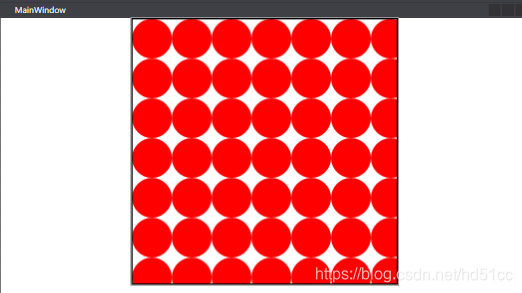
        <Rectangle  Height="400"  Width="400" StrokeThickness="2" Stroke="Black">
            <Rectangle.Fill>
                <DrawingBrush Viewport="0,0,0.15,0.15" TileMode="Tile">
                    <DrawingBrush.Drawing>
                        <GeometryDrawing Brush="Red">
                            <GeometryDrawing.Geometry>
                                <EllipseGeometry RadiusX="10" RadiusY="5" />
                            </GeometryDrawing.Geometry>
                        </GeometryDrawing>
                    </DrawingBrush.Drawing>
                </DrawingBrush>
            </Rectangle.Fill>
</Rectangle>使用对象绘制区域 Visual 。 VisualBrush利用,你可以将内容从应用程序的一个部分复制到另一个区域; 这对于创建反射效果和屏幕的放大部分非常有用。
可以通过两种方式来指定的 Visual 内容 VisualBrush 。
- 创建一个新的 Visual ,并使用它来设置 Visual 的属性 VisualBrush 。
- 使用现有的 Visual ,它创建目标的重复映像 Visual 。 然后,可以使用 VisualBrush 来创建有趣的效果,如反射和放大。
如果BitmapEffect位于画笔的父链中,则不会传播对VisualBrush的可视化树的更新。您可以通过强制更新效果上方对象上的场景来解决此限制。您可以调用InvalidateVisual或包含动画来强制场景更新。

        <Rectangle  Height="400"  Width="400" StrokeThickness="2" Stroke="Black" >
            <Rectangle.Fill>
                <VisualBrush AutoLayoutContent ="False" TileMode="Tile" Viewport="0,0,0.5,0.25">
                    <VisualBrush.Visual >
                        <Button Content="按钮"  Height="20" Width="120"/>
                    </VisualBrush.Visual>
                </VisualBrush>
            </Rectangle.Fill>
        </Rectangle>
预定义画笔
使用 Brushes 类来绘制使用预定义纯色(如或)的对象 AliceBlue Red 。
XAML 中的画笔
下表列出了 Brush 可在 XAML 中使用的不同类型以及它们支持的语法。 有关特定画笔的详细语法信息,请参阅该画笔的类型页。
| 类 | 特性语法 | 对象元素语法 |
|---|---|---|
| SolidColorBrush | 是 | 是 |
| DrawingBrush | 否 | 是 |
| ImageBrush | 否 | 是 |
| LinearGradientBrush | 否 | 是 |
| RadialGradientBrush | 否 | 是 |
| VisualBrush | 否 | 是 |
Geometry
表示一条直线。
若要创建多个连接的线条,请将 LineSegment 或 Polyline 段与 PathFigure 和类一起使用 PathGeometry 。
描述一个二维的矩形。
表示一个圆或椭圆的几何图形。
使用 EllipseGeometry 带有 Path 元素或的类 GeometryDrawing 来绘制椭圆,或使用 Clip 的属性 UIElement 来定义椭圆形剪辑区域。 EllipseGeometry类还有许多其他用途。 有关的详细信息 EllipseGeometry ,请参阅 几何概述。
Ellipse类具有 Fill 、 Stroke 和其他缺少的呈现属性 EllipseGeometry 。 Ellipse类是 FrameworkElement ,因此参与布局系统; 它可用作支持子级的任何元素的内容 UIElement 。
EllipseGeometry另一方面,类只定义椭圆的几何图形,而不能呈现自身。 由于其简易性,其使用范围更广。
表示一个可能由弧、曲线、椭圆、直线和矩形组成的复杂形状。
每个 PathGeometry 对象都定义对象的集合 PathFigure 。 每个 PathFigure 对象都由一个或多个 PathSegment 对象组成,如 ArcSegment 和 LineSegment ,它们实际定义其形状。
PathGeometry 的填充区域 是通过获取所有包含的 PathFigure 对象(其 IsFilled 属性设置为true ) ,并应用 FillRule 来确定封闭区域来定义的。
PathSegment 参考下文。
定义使用 StreamGeometryContext 描述的几何图形。 该几何图形是 PathGeometry 的轻量级替代:它不支持数据绑定、动画或修改。
StreamGeometry当你需要描述复杂的几何图形但不需要支持数据绑定、动画或修改的开销时,请使用。 由于此类的效率, StreamGeometry 该类是描述装饰器的不错选择。
StreamGeometry如果包含 Transform 或任何非描边或未填充段,则无法对其进行序列化。
表示由两个 Geometry 对象的组合定义的二维几何形状。
GeometryCombineMode属性指定如何组合两个几何图形。 请注意, CombinedGeometry 将两个几何图形指定的区域组合在一起,因此,不具有区域 (的几何图形(如) )将 LineGeometry 在组合后消失。
可以通过多种方式组合几何图形:使用类的 GeometryGroup 、 CombinedGeometry 或 Combine 方法 Geometry 。
- GeometryGroup创建一个或多个对象的复合几何图形 Geometry 。
- CombinedGeometry使用指定的布尔运算组合两个对象所描述的区域 Geometry 。
- 类的静态 Combine 方法的 Geometry 行为方式与对象的行为完全相同 CombinedGeometry 。
当使用执行 union 时应谨慎考虑, CombinedGeometry 因为这可能会占用大量的 CPU 资源。 在大多数情况下, GeometryGroup 或的 AddGeometry 工作效果更佳。
CombinedGeometry仅当以下任一条件适用时,才使用:
- 几何操作不是联合。
- 其中的一个几何图形的 FillRule 值为 EvenOdd ,而几何图形是自相交的 (也就是说, FillRule 实际) 。
- 时间不是问题,但如果创建了一次几何,然后缓存了) ,则 (的空间。 通常, CombinedGeometry 生成的输出小于 AddGeometry 。
- 生成的几何图形将在路径动画中描边或使用,并且不会 AddGeometry 提供所需的轮廓。
只能合并2个形状,需要合并多个时请嵌套使用。
表示由其他 Geometry 对象组成的复合几何图形。
复合几何图形对象可以使用 GeometryGroup 、 CombinedGeometry 或调用静态方法来创建 Geometry Combine 。 CombinedGeometry仅创建两个几何图形对象的复合几何图形。 GeometryGroup另一方面,从任意数量的 geometry 对象创建复合几何。
GeometryGroup 使用 FillRule 属性指定其 geometry 对象组合的方式。 有关使用的详细信息,请参阅 如何:控制复合形状的填充 FillRule 。
可以通过多种方式组合几何图形:使用类的 GeometryGroup 、 CombinedGeometry 或 Combine 方法 Geometry 。
- GeometryGroup创建一个或多个对象的复合几何图形 Geometry 。
- CombinedGeometry使用指定的布尔运算组合两个对象所描述的区域 Geometry 。
- 类的静态 Combine 方法的 Geometry 行为方式与对象的行为完全相同 CombinedGeometry 。
值得注意的是,不 GeometryCollection 是自身的复合几何图形,而是由 GeometryGroup 类用来存储 Geometry 对象。
PathSegment
ArcSegment
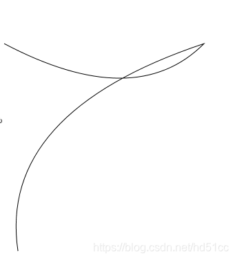
表示两点之间的一条椭圆弧。
使用 PathFigure 对象存储 ArcSegment 对象和其他段。
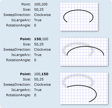
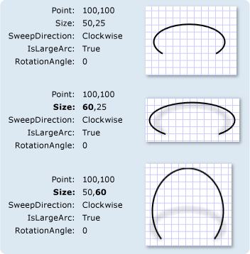
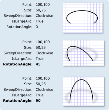
椭圆弧由其起点和终点、x 轴和 y 轴半径、x 轴旋转系数、指示弧是否应大于180度的值以及描述弧线绘制方向的值来定义。 此 ArcSegment 类不包含弧形起始点的属性,它只定义它所表示的弧线的目标点。 圆弧的起点是添加到的的当前点 PathFigure ArcSegment 。
下图演示了不同的终结点、 Size 和 RotationAngle 设置。
IsLargeArc 和 SweepDirection
对于特定位置、大小和旋转的大多数弧形,可以绘制四个不同的弧; IsLargeArc 和 SweepDirection 属性指示要使用的弧线。
在四个候选弧线扫描中,两个表示具有180度或更高的扫描的大弧,两个表示较小的弧,并具有扫描180度或更低。 如果 IsLargeArc 为 true ,则选择两个较大的弧扫描之一; 如果为,则 false 选择一个较小的弧扫描。 其余两个弧线候选项分别按不同方向绘制: Counterclockwise 或 Clockwise 。 SweepDirection属性指定要使用哪一个。
下图显示了不同 IsLargeArc 的和 SweepDirection 设置。
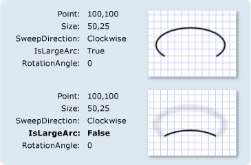
具有不同 IsLargeArc 设置的 ArcSegment 对象
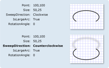
具有不同 SweepDirection 设置的 ArcSegment 对象
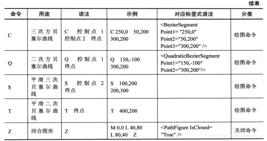
BezierSegment
表示在两个点之间绘制的一条三次方贝塞尔曲线。
使用 PathFigure 对象存储 BezierSegment 对象和其他段。
三次方贝塞尔曲线由四个点定义:起点、终点 (Point3) 和两个控制点 (Point1 和 Point2) 。 此 BezierSegment 类不包含曲线起始点的属性,它只定义终结点。 曲线的起点是添加到的的当前点 PathFigure BezierSegment 。
三次方贝塞尔曲线的两个控制点的行为类似于磁体,可吸引其自身的直线,并生成一条曲线。 第一个控制点 Point1 影响曲线的开始部分; 第二个控制点 Point2 影响曲线的结束部分。 请注意,曲线不一定要经过任一控制点;每个控制点会将线条的一部分向自身移动,但不会通过其自身移动。
LineSegment
在 PathFigure 中的两个点之间创建一条直线。
使用 PathFigure 对象,可以使用 LineSegment 对象和其他段来创建复合形状。
LineSegment类不包含行起点的属性。 直线的起始点是前一段的终点, 如果不存在其他线段,则为PathFigure 的StartPoint 。
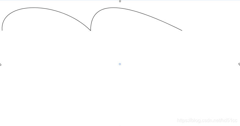
PolyBezierSegment
表示一条或多条三次方贝塞尔曲线。
使用 PathFigure 对象存储 PolyBezierSegment 对象和其他段。
三次方贝塞尔曲线由四个点定义:起点、终点和两个控制点。 PolyBezierSegment通过将属性设置为点的集合,指定一条或多条三次方贝塞尔曲线 Points 。 对于集合中的每三个点,第一个和第二个点指定曲线的两个控制点,第三个点指定终点。 请注意,没有为曲线指定起始点,因为起点与最后一个线段的终点相同。
三次方贝塞尔曲线的两个控制点的行为类似于磁体,可吸引其自身的直线,并生成一条曲线。 第一个控制点影响曲线的开始部分;第二个控制点影响曲线的结束部分。 请注意,曲线不一定要经过任一控制点;每个控制点会将线条的一部分向自身移动,但不会通过其自身移动。
        <Canvas>
            <Path Stroke="Black" StrokeThickness="1">
                <Path.Data>
                    <PathGeometry>
                        <PathGeometry.Figures>
                            <PathFigureCollection>

                                <!-- The StartPoint specifies the starting point of the first curve. -->
                                <PathFigure StartPoint="10,100">
                                    <PathFigure.Segments>
                                        <PathSegmentCollection>

                                            <!-- The PolyBezierSegment specifies two cubic Bezier curves.
                           The first curve is from 10,100 (start point specified above)
                           to 300,100 with a control point of 0,0 and another control
                           point of 200,0. The second curve is from 300,100
                           (end of the last curve) to 600,100 with a control point of 300,0
                           and another control point of 400,0. -->
                                            <PolyBezierSegment Points="0,0 200,0 300,100 300,0 400,0 600,100" />
                                        </PathSegmentCollection>
                                    </PathFigure.Segments>
                                </PathFigure>
                            </PathFigureCollection>
                        </PathGeometry.Figures>
                    </PathGeometry>
                </Path.Data>
            </Path>
        </Canvas>
PolyLineSegment
表示由 PointCollection 定义的线段集合,每个 Point 指定线段的终点。
使用此类在中创建一系列连接的直线 PathFigure 。
<Path Stroke="Black" StrokeThickness="1" >
  <Path.Data>
    <PathGeometry>
      <PathGeometry.Figures>
        <PathFigure StartPoint="10,50">
          <PathFigure.Segments>
            <BezierSegment
              Point1="100,0"
              Point2="200,200"
              Point3="300,100"/>
            <LineSegment Point="400,100" />
            <ArcSegment
              Size="50,50" RotationAngle="45"
              IsLargeArc="True" SweepDirection="Clockwise"
              Point="200,100"/>
          </PathFigure.Segments>
        </PathFigure>

        <PathFigure StartPoint="10,100">
          <PathFigure.Segments>
            <PolyLineSegment Points="50,100 50,150" />
            <QuadraticBezierSegment Point1="200,200" Point2="300,100"/>
          </PathFigure.Segments>
        </PathFigure>
      </PathGeometry.Figures>
    </PathGeometry>
  </Path.Data>
</Path>
PolyQuadraticBezierSegment
表示一系列二次贝塞尔线段。
通过此类,您可以指定用于创建多个二次贝塞尔曲线线段的点的集合。 使用 QuadraticBezierSegment ,可以仅指定两个点来创建单个二次贝塞尔曲线段。
        <Canvas>
            <Path Stroke="Black" StrokeThickness="1">
                <Path.Data>
                    <PathGeometry>
                        <PathGeometry.Figures>
                            <PathFigureCollection>

                                <!-- The StartPoint specifies the starting point of the first curve. -->
                                <PathFigure StartPoint="10,100">
                                    <PathFigure.Segments>
                                        <PathSegmentCollection>

                                            <!-- The PolyQuadraticBezierSegment specifies two Bezier curves.
                           The first curve is from 10,100 (start point specified above)
                           to 300,100 with a control point of 200,200. The second curve
                           is from 200,200 (end of the last curve) to 30,400 with a
                           control point of 0,200. -->
                                            <PolyQuadraticBezierSegment Points="200,200 300,100 0,200 30,400" />
                                        </PathSegmentCollection>
                                    </PathFigure.Segments>
                                </PathFigure>
                            </PathFigureCollection>
                        </PathGeometry.Figures>
                    </PathGeometry>
                </Path.Data>
            </Path>
        </Canvas>
QuadraticBezierSegment
在 PathFigure 中两点之间创建二次贝塞尔曲线。
使用 PathFigure 对象,可以使用 QuadraticBezierSegment 对象和其他段来创建复合形状。
QuadraticBezierSegment类不包含行起点的属性。 直线的起始点是前一段的终点, 如果不存在其他线段,则为PathFigure 的StartPoint 。
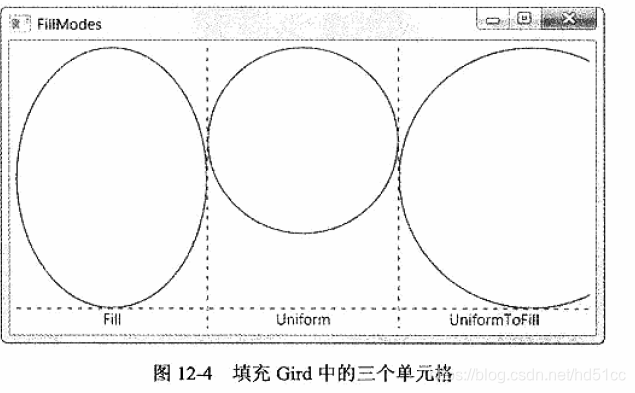
使用ViewBox控件缩放形状
定义一个内容修饰器,以便拉伸或缩放单一子项使其填满可用的控件。
Viewbox只能有一个 Child 。 如果添加其他 Child ,则会 ArgumentException 在运行时引发。
Viewbox常用于矢量图像而不是普通控件。
通常在Viewbox中放置Canvas面板,并在Canvas中放置形状。
Viewbox.Stretch
获取或设置 ViewboxStretch 模式,该模式确定内容适应可用空间的方式。
确定内容适应可用空间的方式的 Stretch。 默认值为 Uniform。
Viewbox.StretchDirection
获取或设置 StretchDirection,它确定缩放如何应用 Viewbox 的内容。
一个 StretchDirection,它确定缩放如何应用于 Viewbox 的内容。 默认值为 Both。
图形裁剪
使用Clip属性进行裁剪。
        <Button Content="按钮" Background="Aqua">
            <Button.Clip>
                <EllipseGeometry Center="395,10" RadiusX="40" RadiusY="10"/>
            </Button.Clip>
        </Button>
XAML范例
最后一个Button是用Shape类元素更改按钮外观。
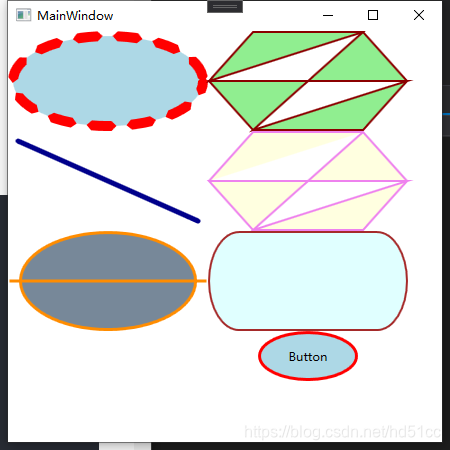
<Window
    x:Class="ShapeDemo.MainWindow"
    xmlns="http://schemas.microsoft.com/winfx/2006/xaml/presentation"
    xmlns:x="http://schemas.microsoft.com/winfx/2006/xaml"
    xmlns:d="http://schemas.microsoft.com/expression/blend/2008"
    xmlns:local="clr-namespace:ShapeDemo"
    xmlns:mc="http://schemas.openxmlformats.org/markup-compatibility/2006"
    Title="MainWindow"
    Width="450"
    Height="450"
    mc:Ignorable="d">
    <Window.Resources>
        <Style TargetType="Button">
            <Setter Property="OverridesDefaultStyle" Value="True" />
            <Setter Property="Template">
                <Setter.Value>
                    <ControlTemplate TargetType="Button">
                        <Grid>
                            <Ellipse Fill="{TemplateBinding Background}"  Stroke="Red" StrokeThickness="3" />
                            <ContentPresenter HorizontalAlignment="Center" VerticalAlignment="Center"  />
                        </Grid>
                    </ControlTemplate>
                </Setter.Value>
            </Setter>
        </Style>
    </Window.Resources>
    <StackPanel Orientation="Horizontal">
        <StackPanel>
            <Ellipse
                Width="200"
                Height="100"
                Fill="LightBlue"
                Stretch="Fill"
                Stroke="Red"
                StrokeDashArray="2"
                StrokeDashCap="Triangle"
                StrokeDashOffset="5"
                StrokeThickness="10" />
            <Line
                Width="200"
                Height="100"
                HorizontalAlignment="Center"
                VerticalAlignment="Center"
                Stroke="DarkBlue"
                StrokeEndLineCap="Round"
                StrokeStartLineCap="Round"
                StrokeThickness="5"
                X1="10"
                X2="190"
                Y1="10"
                Y2="90" />
            <Path
                Width="200"
                Height="100"
                Fill="LightSlateGray"
                Stretch="Fill"
                Stroke="DarkOrange"
                StrokeThickness="3">
                <Path.Data>
                    <GeometryGroup>
                        <EllipseGeometry Center="100,50" RadiusX="80" RadiusY="40" />
                        <LineGeometry StartPoint="10,50" EndPoint="190,50" />
                    </GeometryGroup>
                </Path.Data>
            </Path>
        </StackPanel>
        <StackPanel>
            <Polygon
                Width="200"
                Height="100"
                Fill="LightGreen"
                FillRule="EvenOdd"
                Stretch="Fill"
                Stroke="DarkRed"
                StrokeThickness="2">
                <Polygon.Points>
                    <Point X="10" Y="50" />
                    <Point X="50" Y="10" />
                    <Point X="150" Y="10" />
                    <Point X="190" Y="50" />
                    <Point X="150" Y="90" />
                    <Point X="50" Y="90" />
                    <Point X="10" Y="50" />
                    <Point X="190" Y="50" />
                    <Point X="50" Y="90" />
                    <Point X="150" Y="10" />
                </Polygon.Points>
            </Polygon>
            <Polyline
                Width="200"
                Height="100"
                Fill="LightYellow"
                FillRule="EvenOdd"
                Stretch="Fill"
                Stroke="Violet"
                StrokeThickness="2">
                <Polyline.Points>
                    <Point X="10" Y="50" />
                    <Point X="50" Y="10" />
                    <Point X="150" Y="10" />
                    <Point X="190" Y="50" />
                    <Point X="150" Y="90" />
                    <Point X="50" Y="90" />
                    <Point X="10" Y="50" />
                    <Point X="190" Y="50" />
                    <Point X="50" Y="90" />
                    <Point X="150" Y="10" />
                </Polyline.Points>
            </Polyline>
            <Rectangle
                Width="200"
                Height="100"
                Fill="LightCyan"
                RadiusX="30"
                RadiusY="50"
                Stretch="Fill"
                Stroke="Brown"
                StrokeThickness="2" />
            <Button Width="100" Height="50" Background="LightBlue" Content="Button" />
        </StackPanel>
    </StackPanel>
</Window>


 291
291

 被折叠的 条评论
为什么被折叠?
被折叠的 条评论
为什么被折叠?
 到【灌水乐园】发言


