


本人刚开始玩单片机,非常愿意与各位交流。
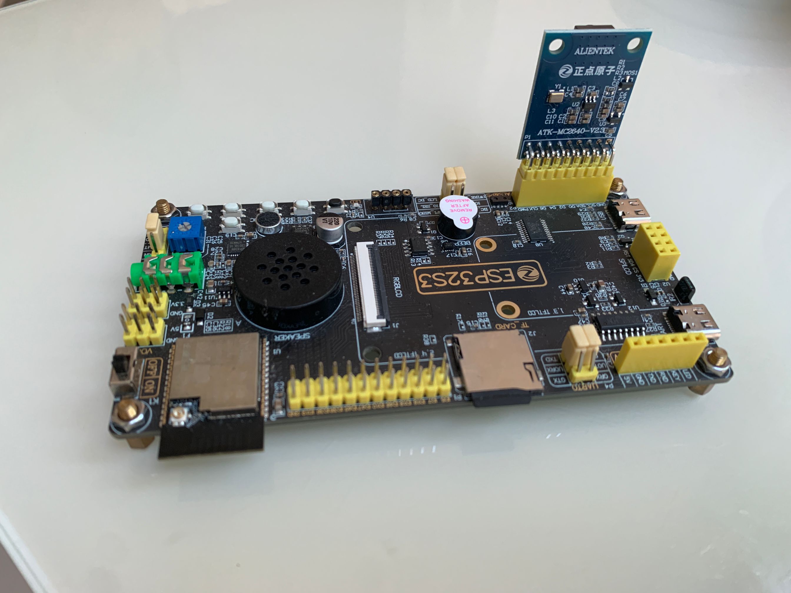
话说上次买的摄像头,不知道为啥,刚玩了半小时就报错探测不到摄像头了,一阵折腾还是不行,但是没了摄像头,还有好多实验没办法往下做了,咬咬牙又花了118大洋买了一个正点原子的ov2640摄像头(这是真的贵啊,都可以买3个其它厂家的同款摄像头了^_^!),再搭配正点原子的esp32s3板,这回总该行了吧。
没想到,原来的代码一通跑下来,仍然报错未探测到摄像头,算了,基于正点原子的例程改一下,结果发现又可以顺利跑起来了。
之前的实验看:正点原子 esp32s3通过网页查看摄像头实时监控-优快云博客
开发板使用:正点原子ATK_DNESP32S3 V1.3
IDE: VSCODE + PLATFORMIO
摄像头模块:ov2640
实验过程依然是通过wifi访问开发板上开的web服务来查看摄像头。
代码包含文件:
camera.h     //拷贝的正点原子的例程
main.cpp
xl9555.cpp   //拷贝的正点原子的例程
xl9555.h     //拷贝的正点原子的例程
代码如下:
camera.h
#ifndef __CAMERA_H
#define __CAMERA_H

#include "Arduino.h"

/* 引脚定义 */
#define OV_SCL_PIN       38
#define OV_SDA_PIN       39
#define OV_D0_PIN        4
#define OV_D1_PIN        5
#define OV_D2_PIN        6
#define OV_D3_PIN        7
#define OV_D4_PIN        15
#define OV_D5_PIN        16
#define OV_D6_PIN        17
#define OV_D7_PIN        18
#define OV_VSYNC_PIN     47
#define OV_HREF_PIN      48
#define OV_PCLK_PIN      45
#define OV_XCLK_PIN      -1
#define OV_RESET_PIN     -1
#define OV_PWDN_PIN      -1

/* 在xl9555.h文件已经有定义
#define OV_RESET
#define OV_PWDN
*/

/* 函数声明 */
uint8_t camera_init(void);            /* 摄像头初始化 */
uint8_t camera_capture_show(void);    /* LCD显示摄像头捕获数据 */

#endif
xl9555.h
#ifndef __XL9555_H
#define __XL9555_H

#include "Arduino.h"

/* 引脚定义 */
#define IIC_SCL       42
#define IIC_SDA       41
#define IIC_INT_PIN   0     /* 需要用跳线帽进行连接 */

#define EXIO_ADDR     0x20  /* 7位器件地址 */

#define IIC_INT       digitalRead(IIC_INT_PIN)

/* IO扩展芯片XL9555的各个IO功能 */
#define KEY0                          XL_PIN_P17  /* 按键0引脚 P17 */
#define KEY1                          XL_PIN_P16  /* 按键1引脚 P16 */
#define KEY2                          XL_PIN_P15  /* 按键2引脚 P15 */
#define KEY3                          XL_PIN_P14  /* 按键3引脚 P14 */
#define SLCD_PWR                      XL_PIN_P13  /* SPI_LCD控制背光引脚 P13 */
#define SLCD_RST                      XL_PIN_P12  /* SPI_LCD复位引脚 P12 */
#define CT_RST                        XL_PIN_P11  /* 触摸屏中断引脚 P11 */
#define LCD_BL                        XL_PIN_P10  /* RGB屏背光控制引脚 P10 */
#define GBC_KEY                       XL_PIN_P07  /* ATK_MODULE接口KEY引脚 P07 */
#define GBC_LED                       XL_PIN_P06  /* ATK_MODULE接口LED引脚 P06 */
#define OV_RESET                      XL_PIN_P05  /* 摄像头复位引脚 P05 */
#define OV_PWDN                       XL_PIN_P04  /* 摄像头待机引脚 P04 */
#define BEEP                          XL_PIN_P03  /* 蜂鸣器控制引脚 P03 */
#define SPK_EN                        XL_PIN_P02  /* 功放使能引脚 P02 */
#define QMA_INT                       XL_PIN_P01  /* QMA6100P中断引脚 P01 */
#define AP_INT                        XL_PIN_P00  /* AP3216C中断引脚 P00 */

/* 器件寄存器 */
#define XL9555_INPUT_PORT0_REG        0           /* 输入寄存器:用于读取P0端口的输入值 */
#define XL9555_INPUT_PORT1_REG        1           /* 输入寄存器:用于读取P1端口的输入值 */
#define XL9555_OUTPUT_PORT0_REG       2           /* 输出寄存器 :用于设置P0端口的输出值 */
#define XL9555_OUTPUT_PORT1_REG       3           /* 输出寄存器 :用于设置P1端口的输出值 */
#define XL9555_INVERSION_PORT0_REG    4           /* 极性反转寄存器:用于当P0端口做为输入时,对输入的电平进行反转处理,即管脚为高电平时,设置这个寄存器中相应的位为1时,读取到的输入寄存器0,1的值就是低电平0 */
#define XL9555_INVERSION_PORT1_REG    5           /* 极性反转寄存器:用于当P1端口做为输入时,对输入的电平进行反转处理,即管脚为高电平时,设置这个寄存器中相应的位为1时,读取到的输入寄存器0,1的值就是低电平0 */
#define XL9555_CONFIG_PORT0_REG       6           /* 配置寄存器:用于配置P0端口的做为输入(1)或是输出(0) */
#define XL9555_CONFIG_PORT1_REG       7           /* 配置寄存器:用于配置P1端口的做为输入(1)或是输出(0) */

/* XL9555各个IO的功能 */
#define XL_PIN_P00       				      0x0001
#define XL_PIN_P01       				      0x0002
#define XL_PIN_P02       				      0x0004
#define XL_PIN_P03       				      0x0008
#define XL_PIN_P04       				      0x0010
#define XL_PIN_P05       				      0x0020
#define XL_PIN_P06       				      0x0040
#define XL_PIN_P07       				      0x0080
#define XL_PIN_P10      				      0x0100
#define XL_PIN_P11      				      0x0200
#define XL_PIN_P12      				      0x0400
#define XL_PIN_P13      				      0x0800
#define XL_PIN_P14      				      0x1000
#define XL_PIN_P15      				      0x2000
#define XL_PIN_P16      				      0x4000
#define XL_PIN_P17      				      0x8000

#define XL_PORT0_ALL_PIN              0x00FF
#define XL_PORT1_ALL_PIN              0xFF00

/* IO配置模式 */
typedef enum
{
  IO_SET_OUTPUT = 0x00,
  IO_SET_INPUT,
} io_mode_t;

/* IO配置输出高低电平 */
typedef enum
{
  IO_SET_LOW = 0x00,
  IO_SET_HIGH,
} io_state_t;

/* 函数声明 */
void xl9555_init(void);                                     /* 初始化IO扩展芯片 */
void xl9555_write_reg(uint8_t reg, uint8_t data);           /* 向XL9555相关寄存器写数据 */
uint8_t xl9555_read_reg(uint8_t reg);                       /* 向XL9555相关寄存器读取数据 */
void xl9555_write_port(uint8_t portx, uint8_t data);        /* 设置XL9555的P0或P1端口的输出状态 */
uint8_t xl9555_read_port(uint8_t portx);                    /* 读取XL9555的P0或P1端口的状态 */
void xl9555_io_config(uint16_t port_pin, io_mode_t mode);   /* 设置XL9555某个IO的模式(输出或输入) */
void xl9555_pin_set(uint16_t port_pin, io_state_t state);   /* 设置XL9555配置为输出功能的IO的输出状态(高电平或低电平) */
uint8_t xl9555_get_pin(uint16_t port_pin);                  /* 获取XL9555配置为输入功能的IO的状态(高电平或低电平) */

#endif
xl9555.cpp
#include "xl9555.h"
#include <Wire.h>

/**
* @brief       初始化IO扩展芯片
* @param       无
* @retval      无
*/
void xl9555_init(void)
{
    pinMode(IIC_INT_PIN, INPUT_PULLUP);     /* 配置中断引脚 */

    Wire.begin(IIC_SDA, IIC_SCL, 400000);   /* 初始化IIC连接 */

    /* 上电先读取一次清除中断标志 */
    xl9555_read_port(0);
    xl9555_read_port(1);
}

/**
 * @brief      向XL9555相关寄存器写数据
 * @param      reg    : 寄存器地址
 * @param      data   : 写入到寄存器的数据
 * @retval     无
 */
void xl9555_write_reg(uint8_t reg, uint8_t data)
{
    Wire.beginTransmission(EXIO_ADDR);        /* 发送从机的7位器件地址到发送队列 */
    Wire.write(reg);                          /* 发送要写入从机寄存器的地址到发送队列 */
    Wire.write(data);                         /* 发送要写入从机寄存器的数据到发送队列 */
    Wire.endTransmission();                   /* IIC 发送 发送队列的数据(不带参数,表示发送stop信号,结束传输) */
}

/**
 * @brief       向XL9555相关寄存器读取数据
 * @param       reg    : 寄存器地址
 * @retval      寄存器的值 / 0xFF:未接收到数据
 */
uint8_t xl9555_read_reg(uint8_t reg)
{
    Wire.beginTransmission(EXIO_ADDR);        /* 发送从机的7位器件地址到发送队列 */
    Wire.write(reg);                          /* 发送要读取从机的寄存器地址到发送队列 */
    Wire.endTransmission(0);                  /* IIC 发送 发送队列的数据(传参为0,表示重新发送一个start信号,保持IIC总线有效连接) */

    Wire.requestFrom(EXIO_ADDR, 1);           /* 主机向从机发送数据请求,并获取到数据 */
    if (Wire.available() != 0)                /* 得到已经接收到的数据字节数 */
    {
        return Wire.read();                   /* 到数据缓冲区读取数据 */
    }

    return 0xFF;
}

/**
 * @brief       设置XL9555的P0或P1端口的输出状态
 * @param       portx : P0 / P1
 * @param       data  : IO的状态(对应8个IO)
 * @retval      无
 */
void xl9555_write_port(uint8_t portx, uint8_t data)
{
    xl9555_write_reg(portx ? XL9555_OUTPUT_PORT1_REG : XL9555_OUTPUT_PORT0_REG, data);
}

/**
 * @brief       读取XL9555的P0或P1端口的状态
 * @param       portx : P0 / P1
 * @retval      IO的状态(对应8个IO)
 */
uint8_t xl9555_read_port(uint8_t portx)
{
    return xl9555_read_reg(portx ? XL9555_INPUT_PORT1_REG : XL9555_INPUT_PORT0_REG);
}

/**
 * @brief       设置XL9555某个IO的模式(输出或输入)
 * @param       port_pin  : 要设置的IO编号,P0~7或P1~7
 * @param       mode      : IO_SET_OUTPUT / IO_SET_INPUT
 * @retval      无
 */
void xl9555_io_config(uint16_t port_pin, io_mode_t mode)
{
    uint8_t config_reg = 0;
    uint8_t config_value = 0;

    config_reg  = xl9555_read_reg(port_pin > XL_PORT0_ALL_PIN ? XL9555_CONFIG_PORT1_REG : XL9555_CONFIG_PORT0_REG);   /* 先读取设置Pin所在的寄存器情况 */

    if (mode == IO_SET_OUTPUT)    /* 根据 mode参数 设置输入输出情况,不能影响其他IO */
    {
        config_value = config_reg & (~(port_pin >> (port_pin > XL_PORT0_ALL_PIN ? 8 : 0)));   /* 得到某个IO设置为输出功能后的PORT值但不影响未设置的其他IO的状态 */
    }
    else
    {
        config_value = config_reg | (port_pin >> (port_pin > XL_PORT0_ALL_PIN ? 8 : 0));      /* 得到某个IO设置为输入功能的PORT值但不影响未设置的其他IO的状态 */
    }

    xl9555_write_reg(port_pin > XL_PORT0_ALL_PIN ? XL9555_CONFIG_PORT1_REG : XL9555_CONFIG_PORT0_REG, config_value);    /* 向配置寄存器设置IO输入输出状态 */
}

/**
 * @brief       设置XL9555配置为输出功能的IO的输出状态(高电平或低电平)
 * @param       port_pin  : 已经设置好输出功能的IO编号
 * @param       state      : IO_SET_LOW / IO_SET_HIGH
 * @retval      无
 */
void xl9555_pin_set(uint16_t port_pin, io_state_t state)
{
    uint8_t pin_reg = 0;
    uint8_t pin_value = 0;

    pin_reg = xl9555_read_reg(port_pin > XL_PORT0_ALL_PIN ? XL9555_OUTPUT_PORT1_REG : XL9555_OUTPUT_PORT0_REG);     /* 先读取设置Pin所在的寄存器情况 */

    if (state == IO_SET_HIGH)    /* 根据 state参数 设置IO的高低电平 */
    {
        pin_value = pin_reg | (port_pin >> (port_pin > XL_PORT0_ALL_PIN ? 8 : 0));          /* 得到某个IO设置为高电平后的PORT值但不影响未设置的其他IO的状态 */
    }
    else
    {
        pin_value = pin_reg & (~(port_pin >> (port_pin > XL_PORT0_ALL_PIN ? 8 : 0)));       /* 得到某个IO设置为低电平后的PORT值但不影响未设置的其他IO的状态 */
    }

    xl9555_write_reg(port_pin > XL_PORT0_ALL_PIN ? XL9555_OUTPUT_PORT1_REG : XL9555_OUTPUT_PORT0_REG, pin_value);   /* 向输出寄存器设置IO高低电平状态 */
}

/**
 * @brief       获取XL9555配置为输入功能的IO的状态(高电平或低电平)
 * @param       port_pin  : 已经设置好输入功能的IO编号
 * @retval      0低电平 / 1高电平
 */
uint8_t xl9555_get_pin(uint16_t port_pin)
{
    uint8_t pin_state = 0;
    uint8_t port_value = 0;

    port_value = xl9555_read_reg(port_pin > XL_PORT0_ALL_PIN ? XL9555_INPUT_PORT1_REG : XL9555_INPUT_PORT0_REG);  /* 读取pin所在port的状态:1没有按下,0按下 */
    pin_state = port_pin >> (port_pin > XL_PORT0_ALL_PIN ? 8 : 0);    /* 假如是PORT1的PIN需要先右移8位 */
    pin_state = pin_state & port_value;                               /* 得到需要查询位的状态 */

    return pin_state ? 1 : 0;
}
main.cpp
#include <Arduino.h>
#include "esp_camera.h"
#include "camera.h"
#include "xl9555.h"
#include <WiFi.h>
#include <WebServer.h>
// WiFi配置 - 请修改为您的网络凭证
const char* ssid = "改为你家的wifi";
const char* password = "改为你家的wifi密码";
// HTTP服务器
WebServer server(80);
camera_fb_t *fb = NULL;
// 提前声明HTTP处理函数
void handleRoot();
void handleStream();
void handleJPG();
void setup() {
Serial.begin(115200);
// 初始化XL9555扩展IO
xl9555_init();
// 摄像头初始化
if(camera_init() != 0) {
Serial.println("摄像头初始化失败!");
while(1) delay(100);
}
// 连接WiFi
WiFi.begin(ssid, password);
while (WiFi.status() != WL_CONNECTED) {
delay(500);
Serial.print(".");
}
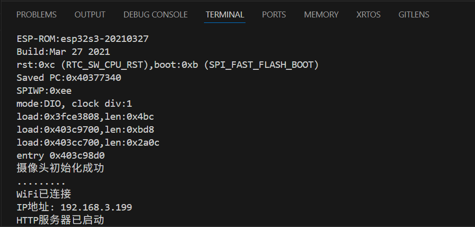
Serial.println("\nWiFi已连接");
Serial.print("IP地址: ");
Serial.println(WiFi.localIP());
// 设置HTTP路由
server.on("/", HTTP_GET, handleRoot);
server.on("/stream", HTTP_GET, handleStream);
server.on("/jpg", HTTP_GET, handleJPG);
server.begin();
Serial.println("HTTP服务器已启动");
}
void loop() {
server.handleClient();
}
/**
* @brief 摄像头初始化
* @param 无
* @retval 0:成功 / 1:失败
*/
uint8_t camera_init(void) {
camera_config_t camera_config;
// 引脚配置
camera_config.pin_d0 = OV_D0_PIN;
camera_config.pin_d1 = OV_D1_PIN;
camera_config.pin_d2 = OV_D2_PIN;
camera_config.pin_d3 = OV_D3_PIN;
camera_config.pin_d4 = OV_D4_PIN;
camera_config.pin_d5 = OV_D5_PIN;
camera_config.pin_d6 = OV_D6_PIN;
camera_config.pin_d7 = OV_D7_PIN;
camera_config.pin_xclk = OV_XCLK_PIN;
camera_config.pin_pclk = OV_PCLK_PIN;
camera_config.pin_vsync = OV_VSYNC_PIN;
camera_config.pin_href = OV_HREF_PIN;
camera_config.pin_sccb_sda = OV_SDA_PIN;
camera_config.pin_sccb_scl = OV_SCL_PIN;
camera_config.pin_pwdn = OV_PWDN_PIN;
camera_config.pin_reset = OV_RESET_PIN;
// 其他配置
camera_config.ledc_channel = LEDC_CHANNEL_0;
camera_config.ledc_timer = LEDC_TIMER_0;
camera_config.xclk_freq_hz = 20000000;
camera_config.pixel_format = PIXFORMAT_JPEG; // 使用JPEG格式
// 优先使用PSRAM
if(psramFound()){
camera_config.frame_size = FRAMESIZE_SVGA; // 800x600
camera_config.jpeg_quality = 12;
camera_config.fb_count = 2;
camera_config.grab_mode = CAMERA_GRAB_LATEST;
camera_config.fb_location = CAMERA_FB_IN_PSRAM;
} else {
camera_config.frame_size = FRAMESIZE_QVGA; // 320x240
camera_config.jpeg_quality = 15;
camera_config.fb_count = 1;
}
// XL9555引脚控制
if (OV_PWDN_PIN == -1) {
xl9555_io_config(OV_PWDN, IO_SET_OUTPUT);
xl9555_pin_set(OV_PWDN, IO_SET_LOW);
}
if (OV_RESET_PIN == -1) {
xl9555_io_config(OV_RESET, IO_SET_OUTPUT);
xl9555_pin_set(OV_RESET, IO_SET_LOW);
delay(20);
xl9555_pin_set(OV_RESET, IO_SET_HIGH);
delay(20);
}
// 初始化摄像头
esp_err_t err = esp_camera_init(&camera_config);
if (err != ESP_OK) {
Serial.printf("摄像头初始化失败: 0x%x", err);
return 1;
}
// 摄像头传感器配置
sensor_t *s = esp_camera_sensor_get();
// 根据摄像头型号设置方向
if (s->id.PID == OV2640_PID) {
s->set_vflip(s, 0); // OV2640不需要垂直翻转
} else {
s->set_vflip(s, 1); // 其他摄像头垂直翻转
}
// 图像参数调整
s->set_brightness(s, 0); // 亮度 (-2~2)
s->set_contrast(s, 0); // 对比度 (-2~2)
s->set_saturation(s, 0); // 饱和度 (-2~2)
s->set_hmirror(s, 0); // 水平镜像
Serial.println("摄像头初始化成功");
return 0;
}
// 根页面处理
void handleRoot() {
String html = "<html>\n"
"<head>\n"
"<title>ESP32-CAM Monitor</title>\n"
"<meta name=\"viewport\" content=\"width=device-width, initial-scale=1\">\n"
"<style>\n"
"body { font-family: Arial; text-align: center; margin: 0; padding: 20px; background-color: #f5f5f5; }\n"
"h1 { color: #333; }\n"
".container { max-width: 800px; margin: 0 auto; }\n"
"img { max-width: 100%; border: 1px solid #ddd; border-radius: 4px; box-shadow: 0 0 10px rgba(0,0,0,0.1); }\n"
".controls { margin: 20px 0; }\n"
"a { display: inline-block; margin: 10px; padding: 10px 20px; background: #4CAF50; color: white; text-decoration: none; border-radius: 4px; }\n"
"</style>\n"
"</head>\n"
"<body>\n"
"<div class=\"container\">\n"
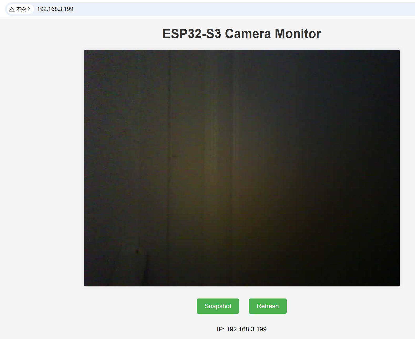
"<h1>ESP32-S3 Camera Monitor</h1>\n"
"<img src=\"/stream\" id=\"video\" alt=\"Live Stream\">\n"
"<div class=\"controls\">\n"
"<a href=\"/jpg\">Snapshot</a>\n"
"<a href=\"javascript:location.reload()\">Refresh</a>\n"
"</div>\n"
"<p>IP: " + WiFi.localIP().toString() + "</p>\n"
"</div>\n"
"<script>\n"
"// Auto-refresh image\n"
"setInterval(function() {\n"
" document.getElementById('video').src = '/stream?' + Date.now();\n"
"}, 100);\n"
"</script>\n"
"</body>\n"
"</html>\n";
server.send(200, "text/html", html);
}
// 视频流处理
void handleStream() {
WiFiClient client = server.client();
// 发送HTTP头
client.println("HTTP/1.1 200 OK");
client.println("Content-Type: multipart/x-mixed-replace; boundary=frame");
client.println();
while (client.connected()) {
fb = esp_camera_fb_get();
if (!fb) {
Serial.println("摄像头捕获失败");
continue;
}
// 发送图像边界
client.println("--frame");
client.println("Content-Type: image/jpeg");
client.println("Content-Length: " + String(fb->len));
client.println();
// 发送图像数据
client.write(fb->buf, fb->len);
client.println();
esp_camera_fb_return(fb);
fb = NULL;
// 短暂延迟以控制帧率
delay(50);
}
}
// 单张图片处理
void handleJPG() {
fb = esp_camera_fb_get();
if (!fb) {
server.send(500, "text/plain", "摄像头捕获失败");
return;
}
// 正确调用send方法
server.send_P(
200,
"image/jpeg",
reinterpret_cast<const char*>(fb->buf),
fb->len
);
esp_camera_fb_return(fb);
fb = NULL;
}platformio.ini
[env:dnesp32s3]
platform = espressif32
board = dnesp32s3
framework = arduino
test_speed = 115200
monitor_speed = 115200
upload_speed = 115200
debug_speed = 115200
编译烧录后,查看monitor:
访问: http://192.168.3.199


 462
462

 被折叠的 条评论
为什么被折叠?
被折叠的 条评论
为什么被折叠?
 到【灌水乐园】发言


