


本文详细探讨了在Cisco CSR1000V IOSXE 17.x环境下L2虚拟专用网络的实验配置,核心网运行OSPF和MPLS。文章首先介绍了VPWS(Virtual Private Wire Service)的多种配置方法,包括AC为物理接口、子接口以及通过PW接口和PW类进行精细控制,并展示了PW状态检查、标签映射和流量验证。接着,深入阐述了HVPLS(Hierarchical Virtual Private LAN Service)的nPE和uPE配置,涵盖VFI建立、全互联PW部署、桥接域配置及uPE侧接入PW冗余,并提供了HVPLS状态的检查方法。最后,简要介绍了本地交换的配置,即在同一PE设备上直接连接两个AC,旨在为读者提供L2虚拟专用网络实际部署和故障排查的全面指导。
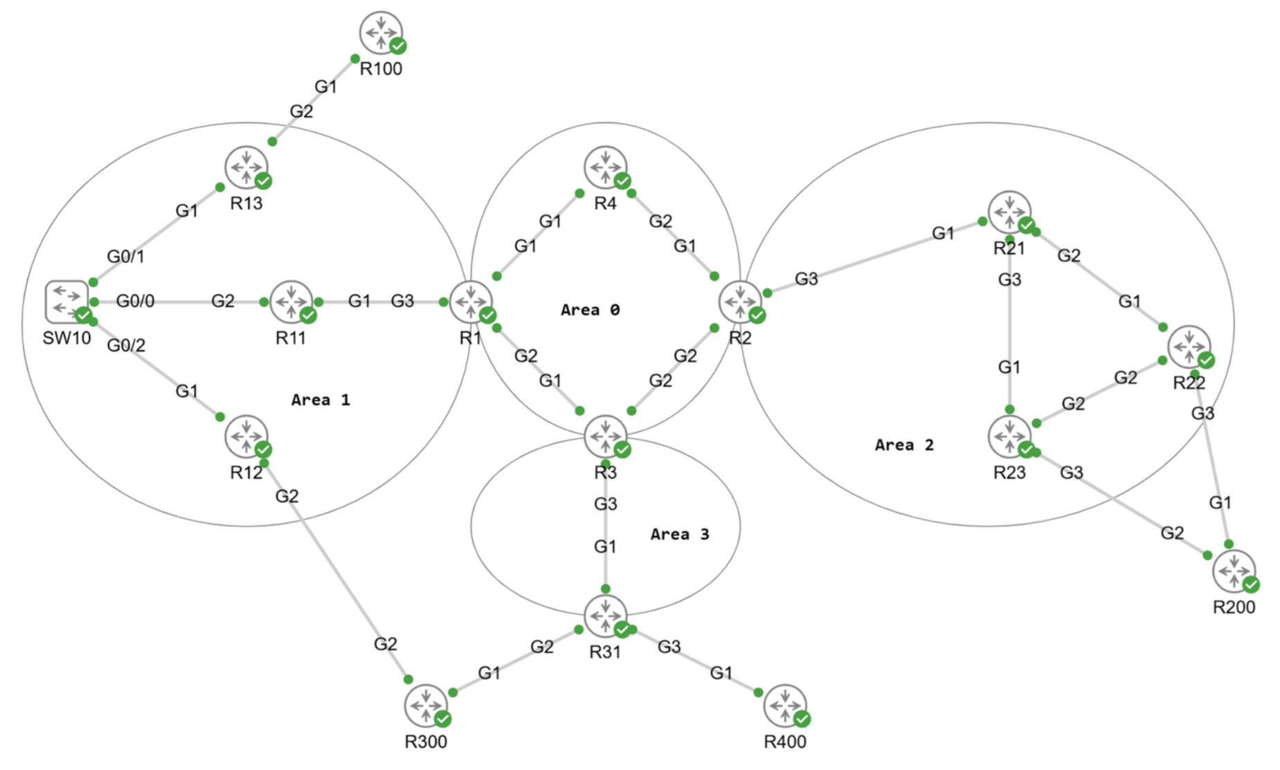
拓扑初始配置,核心网运行OSPF和MPLS,所有的核心网路由器的/32 Lo0地址是可达的也分配了标签。设备为CSR1000V IOSXE 17.x。
1. VPWS配置示例
1.1 Xconnect - AC为物理接口
R13和R22作为连接CE R100和R200的PE,CE端使用物理接口直接连接到PE。
1.1.1 Xconnect配置
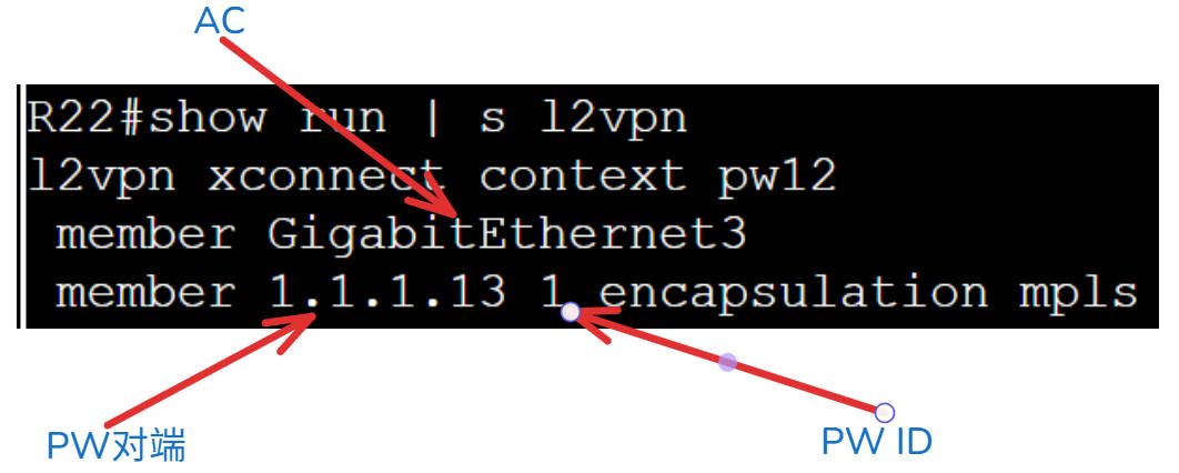
在PE上分别配置Xconnect,里面包括AC和PW的对端。
R13#show run | s l2vpn
l2vpn xconnect context pw12
 member GigabitEthernet2
 member 1.1.1.22 1 encapsulation mpls

R22#show run | s l2vpn
l2vpn xconnect context pw12
 member GigabitEthernet3
 member 1.1.1.13 1 encapsulation mpls
1.1.2 PW相关的检查
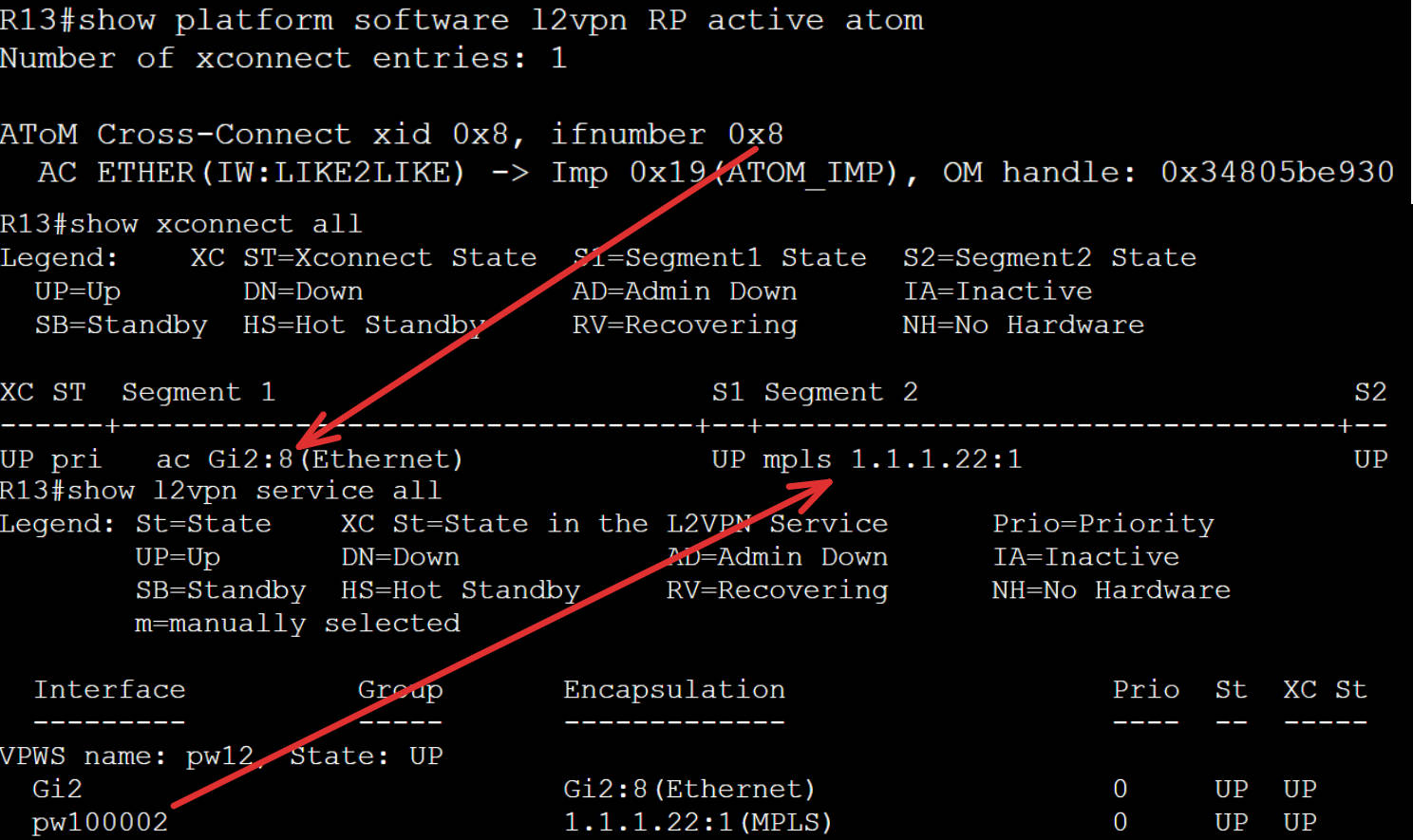
查看Xconnect的状态。因为PW是单向的,所以两侧都要检查。
# 查看Xconnect双向PW
R13#show xc all

XC ST  Segment 1                         S1 Segment 2                         S2
------+---------------------------------+--+---------------------------------+--
UP pri   ac Gi2:8(Ethernet)              UP mpls 1.1.1.22:1                   UP

R22#show xc all

XC ST  Segment 1                         S1 Segment 2                         S2
------+---------------------------------+--+---------------------------------+--
UP pri   ac Gi3:9(Ethernet)              UP mpls 1.1.1.13:1                   UP

R13#show mpls l2transport vc

Local intf     Local circuit              Dest address    VC ID      Status
-------------  -------------------------- --------------- ---------- ----------
Gi2            Ethernet                   1.1.1.22        1          UP

# 查看PW的状态
R13#show l2vpn atom vc

                                       Service
Interface Peer ID         VC ID      Type   Name                     Status
--------- --------------- ---------- ------ ------------------------ ----------
pw100002  1.1.1.22        1          p2p    pw12                     UP

R13#show l2vpn acircuit id
Access circuit info, 1 total:

Eth, 1 circuit:
AC           ID         Instance Circuit  I/f                  Switch   Segment  Rsvd/Chkp/Prov
--------------------------------------------------------------------------------
Eth:8        117440513  1        8        8                    4096     8194     ---- ---- Prov

# 查看PW的标签映射
R13#show mpls l2transport binding
  Destination Address: 1.1.1.22,VC ID: 1
    Local Label:  26
        Cbit: 1,    VC Type: Ethernet,    GroupID: n/a
        MTU: 1500,   Interface Desc: n/a
        VCCV: CC Type: CW [1], RA [2], TTL [3]
              CV Type: LSPV [2]
    Remote Label: 26
        Cbit: 1,    VC Type: Ethernet,    GroupID: 0
        MTU: 1500,   Interface Desc: n/a
        VCCV: CC Type: CW [1], RA [2], TTL [3]
              CV Type: LSPV [2]

R13#show mpls l2transport pwid
AToM Pseudowire IDs: In use: 1, In holddown: 0

       Peer-Address    VCID or
Label  or Local ID     E虚拟专用网络 ID    PWID       In-Use FirstUse ReusedAt FreedAt
------ --------------- ---------- ---------- ------ -------- -------- --------
26     1.1.1.22        1          1          Yes    1d07h Never    Never
1.1.3 图解show命令输出
show xc all的输入解释:
- Segment 1里的Gi2:8,物理接口后面的数字是接口在系统内部的代号。
- Segment 2里的内容是PW的对端PE的Lo0地址,:1是PW ID为1。
- 其实系统内部还是为PW建立了一个接口pw100002。
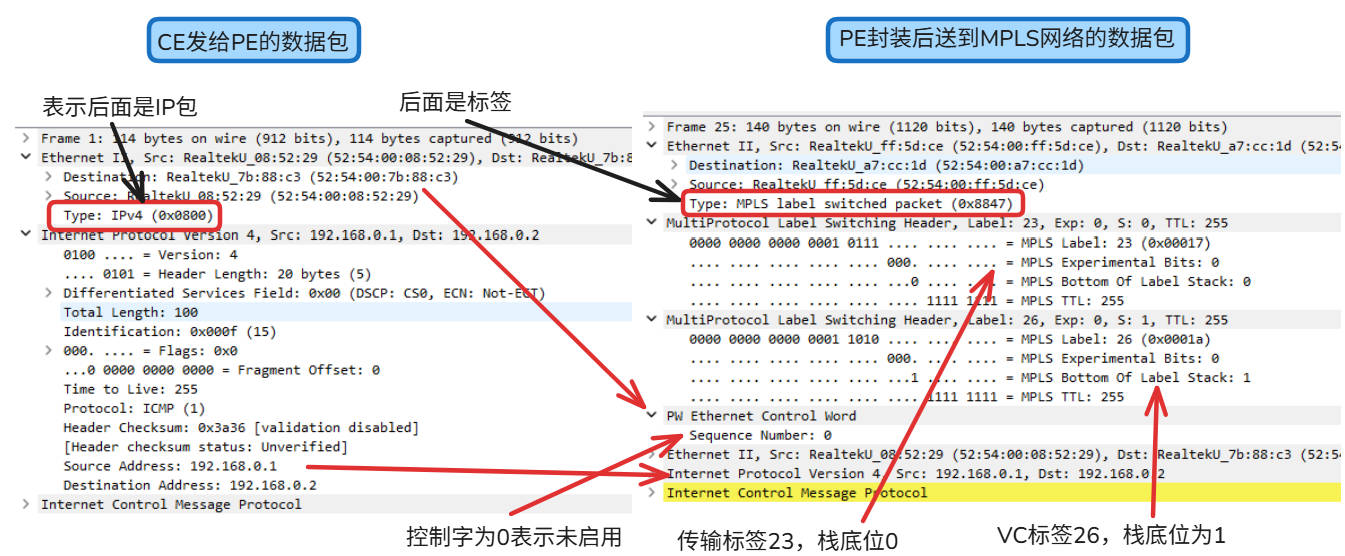
1.1.4 图解抓包检查
我们尝试从一个CE ping另一个CE,是可以ping得通的。
# CE R100可以ping得通CR R200
R100#ping 192.168.0.2
Type escape sequence to abort.
Sending 5, 100-byte ICMP Echos to 192.168.0.2, timeout is 2 seconds:
!!!!!
Success rate is 100 percent (5/5), round-trip min/avg/max = 6/13/44 ms
- 首先PE收到客户发来的原生的数据包。
- LDP对等体之间会沟通是否启用控制字,以太网控制字不是必须的,模拟器这显示是0,表示未启用。
- PE根据接收数据的接口找AC对的对应的VC ID,并压入VC标签。再根据PW的终点,压入到PW终点的传输标签。
- 客户的数据包去除了前导码和校验码,将原来的以太头部和IP头部以及ICMP的数据直接放在控制字的后面。
- PE将数据包发送到MPLS网络,并根据最外层的传输标签达到PW的终点。
1.1.5 AC接口下配置xconnect
除了上述的配置方法外,还支持在AC接口下直接配置PW的方法。另一端的配置方法同上,PW依然可以起来。
从PWID的使用情况来看,删除旧配置,改用接口新配置后,系统内部给PW ID的编号变成2了。原来的PW ID 1依然存在,只是状态变成不使用了。VC ID是不变的,是手工配置且两端需要一致的。
# AC接口的配置
interface GigabitEthernet2
 no ip address
 xconnect 1.1.1.22 1 encapsulation mpls

# PW状态依然是Up的,AC接口没变所以内部接口号:8依然没有变。
R13#show xc all

XC ST  Segment 1                         S1 Segment 2                         S2
------+---------------------------------+--+---------------------------------+--
UP pri   ac Gi2:8(Ethernet)              UP mpls 1.1.1.22:1                   UP

# 但是PW ID变化了,因为将之前的配置方法删除了,在
R13#show l2vpn atom pwid
AToM Pseudowire IDs: In use: 1, In holddown: 1

       Peer-Address    VCID or
Label  or Local ID     E虚拟专用网络 ID    PWID       In-Use FirstUse ReusedAt FreedAt
------ --------------- ---------- ---------- ------ -------- -------- --------
26     1.1.1.22        1          1          Yes    1d07h 1d19h 1d19h
NoLabl 1.1.1.23        1          2          No     1d19h Never    1d19h
1.1.6 PW的配置放到逻辑接口上
可以配置逻辑的PW接口,将对端信息和封装信息都放在PW接口内,把这个接口放到xc的member里。
使用逻辑的PW接口,下面可以配置更丰富的信息。只更改一端的配置,对端配置不变。
# 在对端没有更改配置的情况下,本端的配置
interface pseudowire1
 encapsulation mpls
 neighbor 1.1.1.22 1
 status
 vc type vlan
 control-word include

l2vpn xconnect context pw12
 member GigabitEthernet2
 member pseudowire1

# 因为把VC类型改成以太VLAN模式了,而对端没有设置,模式是以太接口模式。所以有下面的报错,但是被系统忽略了。
*Oct 19 03:22:58.325: %XCONNECT-4-VC_TYPE_INCOMPATIBLE: The 'vc type' command on pseudowire 1.1.1.22:1 is incompatible with xconnect pw12, ignored
*Oct 19 03:22:58.399: %LDP-5-NBRCHG: LDP Neighbor 1.1.1.22:0 (3) is UP[OK]

# 使用PW接口的好处是不需要系统内部分配pw接口号
R13#show l2vpn service all

  Interface          Group       Encapsulation                   Prio  St  XC St
  ---------          -----       -------------                   ----  --  -----
VPWS name: pw12, State: UP
  Gi2                            Gi2:8(Ethernet)                 0     UP  UP
  pw1                            1.1.1.22:1(MPLS)                0     UP  UP

R13#show l2vpn atom vc

                                       Service
Interface Peer ID         VC ID      Type   Name                     Status
--------- --------------- ---------- ------ ------------------------ ----------
pw1       1.1.1.22        1          p2p    pw12                     UP
可以看到的是PW依然是UP的,说明两端的协商达成了一致,让我们查看一下show命令的输入。
- PW,VC都是Up的,VC Type为以太接口模式。
- 压入2层的标签栈,外层的传输标签和内层的VC标签。
- FEC TLV携带的类型128的PWid FEC Element。
- 因为本端开启了Status TLV, 因此Status TLV support显示本端启用,对端支持。
- VCCV的CV使用的MPLS Ping来保证LSP的路径是通的。
- VCCV的CC使用了CW, RA和TTL。
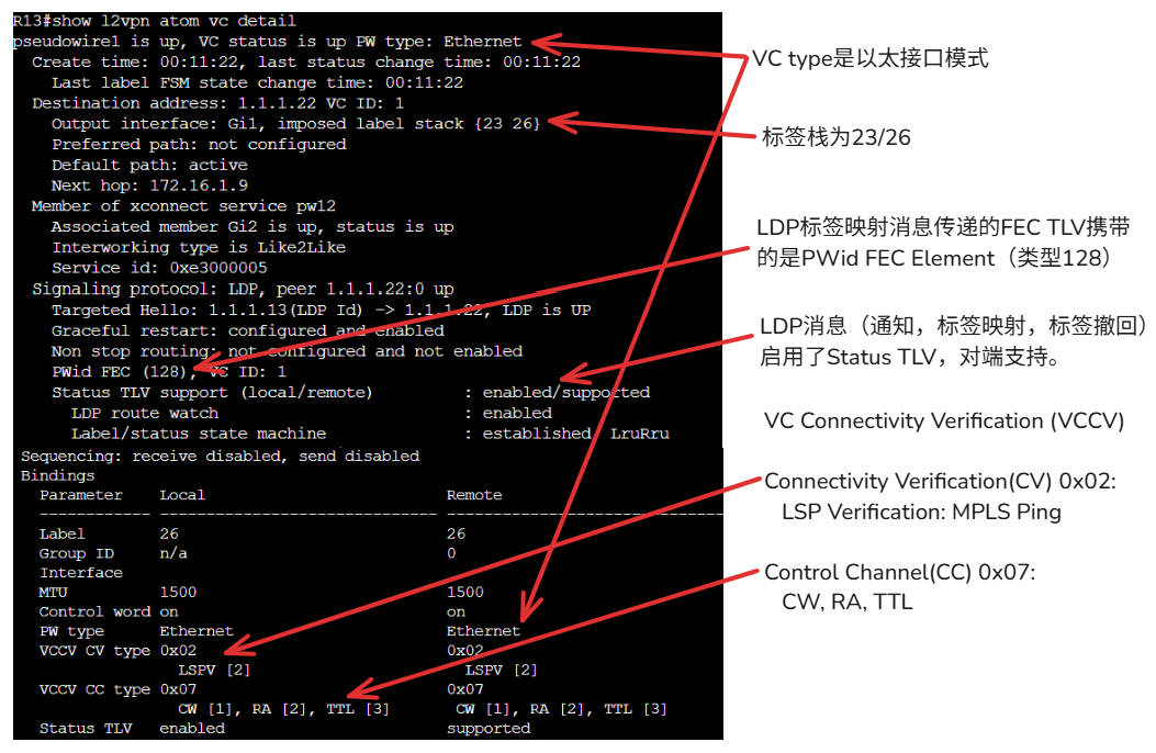
RFC 5085规定的CC Type和CV Type。这就是类型0x02和0x07的出处。
   Control Channel (CC) Types:

      The defined values for CC Types for MPLS PWs are:

         MPLS Control Channel (CC) Types:

         Bit (Value)    Description
         ============   ==========================================
         Bit 0 (0x01) - Type 1: PWE3 Control Word with 0001b as
                        first nibble (PW-ACH, see [RFC4385])
         Bit 1 (0x02) - Type 2: MPLS Router Alert Label
         Bit 2 (0x04) - Type 3: MPLS PW Label with TTL == 1
         Bit 3 (0x08) - Reserved
         Bit 4 (0x10) - Reserved
         Bit 5 (0x20) - Reserved
         Bit 6 (0x40) - Reserved
         Bit 7 (0x80) - Reserved

   Connectivity Verification (CV) Types:

      The defined values for CV Types for MPLS PWs are:

         MPLS Connectivity Verification (CV) Types:

         Bit (Value)    Description
         ============   ==========================================
         Bit 0 (0x01) - ICMP Ping
         Bit 1 (0x02) - LSP Ping
         Bit 2 (0x04) - Reserved
         Bit 3 (0x08) - Reserved
         Bit 4 (0x10) - Reserved
         Bit 5 (0x20) - Reserved
         Bit 6 (0x40) - Reserved
         Bit 7 (0x80) - Reserved
1.1.7 设置PW类并调用类
设置pw class和下面的参数。在AC接口下调用,VPWS的名称和PW接口号都是系统生成的。
pseudowire-class vpws-test
 encapsulation mpls
 control-word

interface GigabitEthernet2
 xconnect 1.1.1.22 1 encapsulation mpls pw-class vpws-test

R13# show l2vpn service all

  Interface          Group       Encapsulation                   Prio  St  XC St
  ---------          -----       -------------                   ----  --  -----
VPWS name: Gi2-8, State: UP
  Gi2                left        Gi2:8(Ethernet)                 0     UP  UP
  pw100006           right       1.1.1.22:1(MPLS)                0     UP  UP
1.2 AC接口是子接口
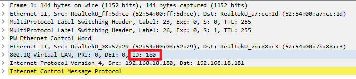
两端CE配置了QinQ,外层Vlan用于区分服务,内层Vlan用于客户网段。
1.2.1 以太接口模式
虽然配置了QinQ,VC Type没指定,默认是以太接口模式
- PE配置子接口承接匹配的外层Vlan。
- 根据外层Vlan来建立不同的PW和PW属性,来达到区分服务的目的。
# CE R100配置
interface GigabitEthernet1.18
 encapsulation dot1Q 18 second-dot1q 180
 ip address 192.168.18.180 255.255.255.0

# CE R200配置
interface GigabitEthernet1.18
 encapsulation dot1Q 18 second-dot1q 180
 ip address 192.168.18.181 255.255.255.0

# PE R13配置
interface GigabitEthernet2.18
 encapsulation dot1Q 18
 xconnect 1.1.1.22 18 encapsulation mpls

interface GigabitEthernet2.20
 encapsulation dot1Q 20
 xconnect 1.1.1.22 20 encapsulation mpls

# PE R22配置
interface GigabitEthernet3.18
 encapsulation dot1Q 18
 xconnect 1.1.1.13 18 encapsulation mpls

interface GigabitEthernet3.20
 encapsulation dot1Q 20
 xconnect 1.1.1.13 20 encapsulation mpls
检查PW的状态:
- 两端两条PW都起来了
R13#show xc all

XC ST  Segment 1                         S1 Segment 2                         S2
------+---------------------------------+--+---------------------------------+--
UP pri   ac Gi2.18:18(Eth VLAN)          UP mpls 1.1.1.22:18                  UP
UP pri   ac Gi2.20:20(Eth VLAN)          UP mpls 1.1.1.22:20                  UP

R22#show xc all

XC ST  Segment 1                         S1 Segment 2                         S2
------+---------------------------------+--+---------------------------------+--
UP pri   ac Gi3.18:18(Eth VLAN)          UP mpls 1.1.1.13:18                  UP
UP pri   ac Gi3.20:20(Eth VLAN)          UP mpls 1.1.1.13:20                  UP
通过抓包可以看到在MPLS网络,外层的S-VLAN被剥离了,内层的C-VLAN被留了下来。
1.2.2 EVC配置模式
虽然我设置了vc type为Vlan,但是总会有报错。所以以太VLAN模式的配置没有成功,不知道是不是模拟器不支持的原因。在模拟器上只能以PW接口的形式才能配上VC Type。
interface GigabitEthernet2
 no ip address
 service instance 18 ethernet
  encapsulation dot1q 18
  rewrite ingress tag pop 1 symmetric
 !
 service instance 20 ethernet
  encapsulation dot1q 20
  rewrite ingress tag pop 1 symmetric
 !
interface pseudowire18
 encapsulation mpls
 neighbor 1.1.1.22 18
 vc type vlan
 !
interface pseudowire20
 encapsulation mpls
 neighbor 1.1.1.22 20
 vc type vlan

l2vpn xconnect context vpws18
 member GigabitEthernet2 service-instance 18
 member pseudowire18
l2vpn xconnect context vpws20
 member GigabitEthernet2 service-instance 20
 member pseudowire20
2. HVPLS
HVPLS的配置和VPLS类似,只不过原来的AC部分换成了PW。全互联的VPLS跑在nPE之间,uPE连接AC并同通过接入的PW连接到1个或2个nPE上。因此HVPLS的配置也就是两部分,一部分在nPE上,一部分在uPE上。
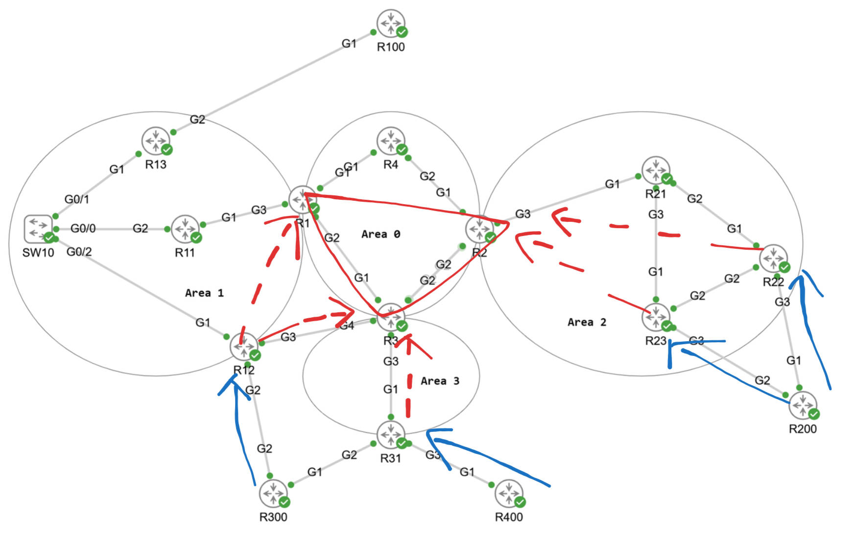
2.1 拓扑图
- R1 - R2 - R3是全互联的VFI,会进行MAC的学习和老化等动作。
- R12到2个nPE有一主一备的PE,下联一个AC到R300。
- 2个uPE下面各有一个AC连接到R200,各自有一条PW到R2。
2.2 nPE配置
- 在所有的nPE上配置相同的VFI,虚拟专用网络 ID要相同。
- 手工指定参加这个VFI的nPE,并建立全互联的PW。
- 将VFI和下联的PW放到一个桥接域里,这样虚拟MAC表可以从VFI其他的PW或是接入PW学习到MAC,这个行为和普通的交换机就非常类似了。
# R1配置

l2vpn vfi context HVPLS
 vpn id 100
 member 1.1.1.3 encapsulation mpls
 member 1.1.1.2 encapsulation mpls

bridge-domain 100
 member vfi HVPLS
 member 1.1.1.12 100 encapsulation mpls

# R2配置

l2vpn vfi context HVPLS
 vpn id 100
 member 1.1.1.3 encapsulation mpls
 member 1.1.1.1 encapsulation mpls

bridge-domain 100
 member vfi HVPLS
 member 1.1.1.23 100 encapsulation mpls
 member 1.1.1.22 100 encapsulation mpls

# R3配置

l2vpn vfi context HVPLS
 vpn id 100
 member 1.1.1.2 encapsulation mpls
 member 1.1.1.1 encapsulation mpls

bridge-domain 100
 member vfi HVPLS
 member 1.1.1.12 100 encapsulation mpls
 member 1.1.1.31 100 encapsulation mpls
2.3 uPE配置
- 配置接入PW连接AC和VFI。
- 在有主备PW的时候,需要设置PW所在的组以及PW的优先级
# R31配置

l2vpn xconnect context HVPLS
 member GigabitEthernet3 service-instance 100
 member 1.1.1.3 100 encapsulation mpls

# R22/R23配置

l2vpn xconnect context HVPLS
 member GigabitEthernet3 service-instance 100
 member 1.1.1.2 100 encapsulation mpls

# R12配置

l2vpn xconnect context HVPLS
 member GigabitEthernet2 service-instance 100
 member 1.1.1.3 100 encapsulation mpls group HVPLS100 priority 1
 member 1.1.1.1 100 encapsulation mpls group HVPLS100 priority 2
2.4 检查HVPLS的状态
检查nPE的状态。
- VFI里包括到其他nPE的PW以及到uPE的PW。
- BD还包括学到动态学到的MAC,也可以手动清空MAC地址表。
R2#show l2vpn vfi
Legend: RT=Route-target, S=Split-horizon, Y=Yes, N=No

VFI name: HVPLS, state: up, type: multipoint, signaling: LDP
  虚拟专用网络 ID: 100
  Bridge-Domain 100 attachment circuits:
  Pseudo-port interface: pseudowire100001
  Interface          Peer Address     VC ID        S
  pseudowire100005   1.1.1.23         100          N
  pseudowire100004   1.1.1.22         100          N
  pseudowire100003   1.1.1.3          100          Y
  pseudowire100002   1.1.1.1          100          Y

R2#show bridge-domain 100
Bridge-domain 100 (4 ports in all)
State: UP                    Mac learning: Enabled
Aging-Timer: 300 second(s)
Maximum address limit: 65536
    vfi HVPLS neighbor 1.1.1.1 100
    vfi HVPLS neighbor 1.1.1.3 100
    vfi HVPLS neighbor 1.1.1.23 100
    vfi HVPLS neighbor 1.1.1.22 100
   AED MAC address    Policy  Tag       Age  Pseudoport
   0   001E.E529.A7BF forward dynamic   42   HVPLS.404012
   0   001E.F6B1.3EBF forward dynamic   43   HVPLS.404011

R2#clear bridge-domain 100 mac table
检查uPE的状态
- 只有R12是具有接入PW冗余的配置
- 两条PW,一主一备,下联是同一个AC。
R12#show xconnect name HVPLS
Legend:    XC ST=Xconnect State  S1=Segment1 State  S2=Segment2 State
  UP=Up       DN=Down            AD=Admin Down      IA=Inactive
  SB=Standby  HS=Hot Standby     RV=Recovering      NH=No Hardware

XC ST  Segment 1                         S1 Segment 2                         S2
------+---------------------------------+--+---------------------------------+--
UP pri   ac Gi2:100(Eth VLAN)            UP mpls 1.1.1.3:100                  UP
IA pri   ac Gi2:100(Eth VLAN)            UP mpls 1.1.1.1:100                  SB
检查CE的状态
- 可以学到其他CE的ARP。
R400#show ip arp
Protocol  Address          Age (min)  Hardware Addr   Type   Interface
Internet  192.168.100.1           0   5254.0008.5229  ARPA   BDI100
Internet  192.168.100.2           0   001e.e529.a7bf  ARPA   BDI100
Internet  192.168.100.4           -   001e.f6b1.3ebf  ARPA   BDI100
3. 本地交换
本地交换就是将2个AC放到一起,不通过MPLS直接传输流量。本质还是PW,常规是一段是PW一段是AC,而本地交换是2段都是AC。可以看到PW是起来的,但是模拟器的原因,CE无法互ping。
# R31配置

l2vpn xconnect context localconnect
 member GigabitEthernet2 service-instance 200
 member GigabitEthernet3 service-instance 200

R31#show l2vpn service xconnect name localconnect
Legend: St=State    XC St=State in the L2虚拟专用网络 Service      Prio=Priority
        UP=Up       DN=Down            AD=Admin Down      IA=Inactive
        SB=Standby  HS=Hot Standby     RV=Recovering      NH=No Hardware
        m=manually selected

  Interface          Group       Encapsulation                   Prio  St  XC St
  ---------          -----       -------------                   ----  --  -----
VPWS name: localconnect, State: UP
  Gi2                            Gi2:200(Eth VLAN)               0     UP  UP
  Gi3                            Gi3:200(Eth VLAN)               0     UP  UP
📚 延伸阅读
更多内容持续更新于我的博客:https://www.zenseek.site


 83
83

 被折叠的 条评论
为什么被折叠?
被折叠的 条评论
为什么被折叠?
 到【灌水乐园】发言


