


Linux/安卓系统使用CH347转接SPI功能有三种应用方式:
1. 使用CH34X_MPHSI_Master总线驱动为系统扩展原生SPI Master,此方式无需进行单独的应用层编程;
2. 使用CH341PAR_LINUX字符设备驱动,此方式需要配合使用厂商提供的库文件,编程访问设备功能;
3. 使用CH341PAR_ANDROID免驱APP,基于安卓原生USB Host API进行二次开发,此方式无需设备驱动;
基于方式一,可参考如下几篇博客:
基于CH347实现USB扩展SPI/I2C/GPIO Master主机应用方案_扩展spi芯片_PC技术小能手的博客-优快云博客在安卓/Linux主机上经常会遇到CPU原生SPI/I2C/GPIO Master资源通道不够或者功性能不满足实际产品需求的情况,基于USB2.0高速USB转接芯片CH347,配合厂商提供的USB转MPHSI(Multi Peripheral Serial Line)Master总线驱动(CH34X-MSPI-Master)可轻松实现为系统扩展SPI和I2C总线、GPIO Expander、中断信号等。_扩展spi芯片![]() https://blog.youkuaiyun.com/WCH_TechGroup/article/details/130093377CH34X-MPHSI高速Master扩展应用—SPI设备调试_PC技术小能手的博客-优快云博客本文介绍,基于USB2.0高速USB转接芯片CH347,配合厂商提供的USB转MPHSI(Multi Protocol High-Speed Serial Interface)Master总线驱动(CH34X-MPHSI-Master)为系统扩展SPI总线的用法,除此之外,还可以扩展I2C总线和GPIO等资源。驱动软件正常工作后,会在系统下创建新的SPI Master,拥有独立的bus num,原SPI器件的设备驱动可直接通过DTS配置文件或者sysfs节点挂载到该总线上,原有设备驱动无需任何修改。
https://blog.youkuaiyun.com/WCH_TechGroup/article/details/130093377CH34X-MPHSI高速Master扩展应用—SPI设备调试_PC技术小能手的博客-优快云博客本文介绍,基于USB2.0高速USB转接芯片CH347,配合厂商提供的USB转MPHSI(Multi Protocol High-Speed Serial Interface)Master总线驱动(CH34X-MPHSI-Master)为系统扩展SPI总线的用法,除此之外,还可以扩展I2C总线和GPIO等资源。驱动软件正常工作后,会在系统下创建新的SPI Master,拥有独立的bus num,原SPI器件的设备驱动可直接通过DTS配置文件或者sysfs节点挂载到该总线上,原有设备驱动无需任何修改。![]() https://blog.youkuaiyun.com/WCH_TechGroup/article/details/133349658本篇博客仅对于方式二做重点介绍:
https://blog.youkuaiyun.com/WCH_TechGroup/article/details/133349658本篇博客仅对于方式二做重点介绍:
一、应用框图

二、资源列表

demo:应用软件示例
driver:驱动软件
lib:应用库文件,提供大部分CPU架构的动态库和静态库
三、工作原理
驱动软件正常工作时,会自动在系统/dev目录下创建字符设备,名称为:/dev/ch34x_pis*。基于此节点设备,配合 libch347 动态库,ch347demo应用程序实现对 CH347 芯片的硬件资源的访问。
此方式适用于不需要依赖于原有外设驱动工作的应用场景,使用字符设备实现对于外设的读写功能。类似于串口应用,通过访问 /dev/tty* 设备实现相应设备的:打开、关闭、读写等操作。
四、使用步骤
使用HID驱动模式,直接使用系统自带的 hidraw 驱动即可,使用厂商驱动模式,需要编译使用 CH341PAR_LINUX 资料中driver下的驱动文件,链接地址:CH341PAR_LINUX.ZIP - 南京沁恒微电子股份有限公司USB转JTAG/SPI/I2C/并口/GPIO等接口的Linux设备驱动程序,支持CH341的USB转SPI/I2C/EPP并口/MEM并口等,支持CH347的480Mbps高速USB转JTAG/SPI/I2C/GPIO等,支持32/64位操作系统。![]() https://www.wch.cn/downloads/CH341PAR_LINUX_ZIP.htmlhttps://github.com/WCHSoftGroup/ch341par_linux
https://www.wch.cn/downloads/CH341PAR_LINUX_ZIP.htmlhttps://github.com/WCHSoftGroup/ch341par_linux![]() https://github.com/WCHSoftGroup/ch341par_linux驱动使用流程如下:
https://github.com/WCHSoftGroup/ch341par_linux驱动使用流程如下:
(1)驱动加载
1. unzip CH341PAR.ZIP
2. cd driver
3. sudo make install

插入CH347硬件设备,此时会自动在 /dev 目录下创建字符设备:ch34x_pis*,如下所示:
![]()
至此,代表驱动程序和芯片工作正常。
(2)拷贝库文件至系统库路径下,此处以X64 CPU的 ch347 动态库为例:
sudo cp lib/x64/dynamic/libch347.so /usr/lib(3)应用编程—SPI 主机模式 API介绍
/**
 * CH347OpenDevice - open device
 * @pathname: device path in /dev directory
 *
 * The function return positive file descriptor if successful, others if fail.
 */
extern int CH347OpenDevice(const char *pathname);

/**
 * CH347CloseDevice - close device
 * @fd: file descriptor of device
 *
 * The function return true if successful, false if fail.
 */
extern bool CH347CloseDevice(int fd);

/**
 * CH347SPI_SetDataBits - SPI data bits setting
 * @fd: file descriptor of device
 * @iDataBits: 0: 8bit, 1: 16bit
 *
 * The function return true if successful, false if fail.
 */
extern bool CH347SPI_SetDataBits(int fd, uint8_t iDataBits);

/**
 * CH347SPI_Init - SPI interface initialization
 * @fd: file descriptor of device
 * @SpiCfg: pointer to SPI configuration, SPI frequency could be set by SpiCfg->iClock or CH347SPI_SetFrequency API, the latter is preferred
 *
 * The function return true if successful, false if fail.
 */
extern bool CH347SPI_Init(int fd, mSpiCfgS *SpiCfg);


/**
 * CH347SPI_SetChipSelect - SPI chip selection initialization
 * @fd: file descriptor of device
 * @iEnableSelect: low 8 bits: CS1, high 8 bits: CS2, byte value -> 1: set CS, 0: ignore CS setting
 * @iChipSelect: low 8 bits: CS1, high 8 bits: CS2, CS output, byte value -> 1: set CS, 0: cancel CS
 * @iIsAutoDeativeCS: low 16 bits: CS1, high 16 bits: CS2, automatically undo the CS after operation completed
 * @iActiveDelay: low 16 bits: CS1, high 16 bits: CS2, delay time of read and write operation after setting CS, unit: us
 * @iDelayDeactive: low 16 bits: CS1, high 16 bits: CS2,, delay time of read and write operation after canceling CS, unit: us
 *
 * The function return true if successful, false if fail.
 */
extern bool CH347SPI_SetChipSelect(int fd, uint16_t iEnableSelect, uint16_t iChipSelect, int iIsAutoDeativeCS, int iActiveDelay, int iDelayDeactive);

/**
 * CH347SPI_ChangeCS - SPI CS setting, must call CH347SPI_Init first
 * @fd: file descriptor of device
 * @iStatus: 0: cancel CS, 1: set CS
 *
 * The function return true if successful, false if fail.
 */
extern bool CH347SPI_ChangeCS(int fd, uint8_t iStatus);

/**
 * CH347SPI_Write - write SPI data
 * @fd: file descriptor of device
 * @ignoreCS: ignore SPI chip select while true, else auto set CS
 * @iChipSelect: SPI chip select, ignore while BIT7 is 0, valid while BIT7 is 1
 * @iLength: length to write
 * @iWriteStep: per write length
 * @ioBuffer: pointer to write buffer
 *
 * The function return true if successful, false if fail.
 */
extern bool CH347SPI_Write(int fd, bool ignoreCS, uint8_t iChipSelect, int iLength, int iWriteStep, void *ioBuffer);

/**
 * CH347SPI_Read - read SPI data
 * @fd: file descriptor of device
 * @ignoreCS: ignore SPI chip select while true, else auto set CS
 * @iChipSelect: SPI chip select, ignore while BIT7 is 0, valid while BIT7 is 1
 * @iLength: length to write
 * @oLength: pointer to read length
 * @ioBuffer: pointer to buffer, store data to be written from MOSI, and return data to be read from MISO
 *
 * The function return true if successful, false if fail.
 */
extern bool CH347SPI_Read(int fd, bool ignoreCS, uint8_t iChipSelect, int iLength, uint32_t *oLength, void *ioBuffer);

/**
 * CH347SPI_WriteRead - write then read SPI data
 * @fd: file descriptor of device
 * @ignoreCS: ignore SPI chip select while true, else auto set CS
 * @iChipSelect: SPI chip select, ignore while BIT7 is 0, valid while BIT7 is 1
 * @iLength: data length to xfer
 * @ioBuffer: pointer to buffer, store data to be written from MOSI, and return data to be read from MISO
 *
 * The function return true if successful, false if fail.
 */
extern bool CH347SPI_WriteRead(int fd, bool ignoreCS, uint8_t iChipSelect, int iLength, void *ioBuffer);
如上API接口函数,根据不同的业务场景可以选用不同的函数。
CH347SPI_Write: 适用于单次SPI通讯长度固定,或者类似SPI FLASH有固定页/扇区大小的器件,可以提升效率。
CH347SPI_Read:适用于单次SPI通讯长度固定,或者类似SPI FLASH有固定页/扇区大小的器件,可以提升效率。
CH347SPI_WriteRead:适用于所有类型的SPI通讯,交换传输,数据从MOSI输出,同时从MISO上采集数据保存到 ioBuffer 缓冲区中。
CH347 SPI主机模式操作流程:

注:
1、CH347SPI_SetDataBits 用于启用/禁用 SPI 16位读写功能,此API为可选项。
2、CH347SPI_ChangeCS 用于手动控制芯片的 CS 片选引脚,此API为可选项。
CH347SPI_WriteRead 函数说明
ignoreCS:此次xfer传输是否忽略片选设置,true:传输开始和结束不操作片选信号,false:传输开始和结束自动使能和失能片选信号(当 iChipSelect 设定有效时)
iChipSelect:SPI 片选设置,BIT7为1,片选有效,BIT7为0,撤销片选
iLength:此次xfer数据传输的长度
ioBuffer:需要xfer传输的缓冲区,由于SPI是exchange交换传输,因此该缓冲区内容会先经过MOSI信号线对外输出,然后该API成功返回后,其内容是从MISO信号线上采集的数据。
示例:
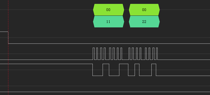
uint8_t ioBuffer[2] = {0x11, 0x22};

CH347SPI_WriteRead(fd, false, 0x80, 2, ioBuffer);
此时,MOSI输出2个字节数据 0x11 和 0x22,然后返回 MISO数据。
图1:MISO悬空(高电平)
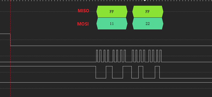
图2:MISO接GND(低电平)
 如上为CH347的SPI功能使用说明,其他平台上Linux和Android系统上接口函数均保持类似,可直接参考移植。


 5071
5071


 到【灌水乐园】发言


