


 本文详细介绍了企业网络的搭建过程,包括配置接入层、核心层交换机,设置VRRP主备备份,配置OSPF路由协议,实现负载均衡及限速等功能。此外还涉及了出口路由器的配置,如NAT转换、静态路由、ACL等。
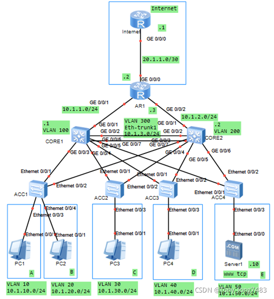
(一) 配置接入层交换机
1.配置ACC1
(1)创建vlan
[ACC1]vlan batch 10 20
(2)配置ACC1连接CORE1和CORE2的接口,透传A和B的VLAN
[ACC1-Ethernet0/0/1]port link-type trunk
[ACC1-Ethernet0/0/1]port trunk allow-pass vlan 10 20
[ACC1-Ethernet0/0/2]port link-type trunk
[ACC1-Ethernet0/0/2]port trunk allow-pass vlan 10 20
(3)配置ACC1连接用户的接口,使各部门加入VLAN
[ACC1-Ethernet0/0/3]port link-type access
[ACC1-Ethernet0/0/3]port default vlan 10
[ACC1-Ethernet0/0/4]port link-type access
[ACC1-Ethernet0/0/4]port default vlan 20
(4)配置BPDU保护功能,加强网络的稳定性
[ACC1]stp bpdu-protection
2.配置ACC2
(1)创建vlan
[ACC2]vlan batch 30
(2)配置ACC2连接CORE1和CORE2的接口,透传C的VLAN
[ACC2-Ethernet0/0/1]port link-type trunk
[ACC2-Ethernet0/0/1]port trunk allow-pass vlan 30
[ACC2-Ethernet0/0/2]port link-type trunk
[ACC2-Ethernet0/0/2]port trunk allow-pass vlan 30
(3)配置ACC2连接用户的接口,使各部门加入VLAN
[ACC2-Ethernet0/0/3]port link-type access
[ACC2-Ethernet0/0/3]port default vlan 30
(4)配置BPDU保护功能,加强网络的稳定性
[ACC2]stp bpdu-protection
3.配置ACC3
(1)创建vlan
[ACC3]vlan batch 40
(2)配置ACC3连接CORE1和CORE2的接口,透传D的VLAN
[ACC3-Ethernet0/0/1]port link-type trunk
[ACC3-Ethernet0/0/1]port trunk allow-pass vlan 40
[ACC3-Ethernet0/0/2]port link-type trunk
[ACC3-Ethernet0/0/2]port trunk allow-pass vlan 40
(3)配置ACC3连接用户的接口,使各部门加入VLAN
[ACC3-Ethernet0/0/3]port link-type access
[ACC3-Ethernet0/0/3]port default vlan 40
(4)配置BPDU保护功能,加强网络的稳定性
[ACC3]stp bpdu-protection
4.配置ACC4
(1)创建vlan
[ACC4]vlan batch 50
(2)配置ACC4连接CORE1和CORE2的接口,透传E的VLAN
[ACC4-Ethernet0/0/1]port link-type trunk
[ACC4-Ethernet0/0/1]port trunk allow-pass vlan 50
[ACC4-Ethernet0/0/2]port link-type trunk
[ACC4-Ethernet0/0/2]port trunk allow-pass vlan 50
(3)配置ACC4连接用户的接口,使各部门加入VLAN
[ACC4-Ethernet0/0/3]port link-type access
[ACC4-Ethernet0/0/3]port default vlan 50
(4)配置BPDU保护功能,加强网络的稳定性
[ACC4]stp bpdu-protection
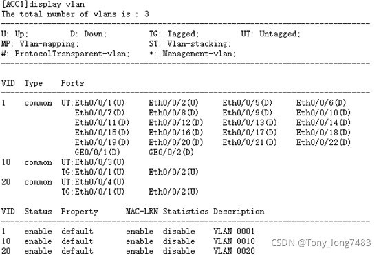
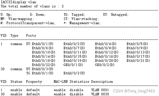
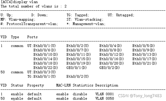
5.查看配置结果
blog.csdnimg.cn/cae613410b8c4686aa961313294bee01.png?x-oss-process=image/watermark,type_ZHJvaWRzYW5zZmFsbGJhY2s,shadow_50,text_Q1NETiBAVG9ueV9sb25nNzQ4Mw==,size_14,color_FFFFFF,t_70,g_se,x_16)

(二)配置核心层交换机
1.配置CORE1
(1)创建其与接入交换机、备份设备以及园区出口路由器互通的VLAN
[CORE1]vlan batch 10 20 30 40 50 100 300
(2)配置用户侧的接口VLAN和VLANIF,VLANIF接口用于部门之间互访
[CORE1-GigabitEthernet0/0/3]port link-type trunk
[CORE1-GigabitEthernet0/0/3]port trunk allow-pass vlan 10 20
[CORE1]int Vlanif 10
[CORE1-Vlanif10]ip add 10.1.10.1 24
[CORE1-Vlanif10]int Vlanif 20
[CORE1-Vlanif20]ip add 10.1.20.1 24
[CORE1-GigabitEthernet0/0/4]port link-type trunk
[CORE1-GigabitEthernet0/0/4]port trunk allow-pass vlan 30
[CORE1]int Vlanif 30
[CORE1-Vlanif30]ip add 10.1.30.1 24
[CORE1-GigabitEthernet0/0/5]port link-type trunk
[CORE1-GigabitEthernet0/0/5]port trunk allow-pass vlan 40
[CORE1]int Vlanif 40
[CORE1-Vlanif40]ip add 10.1.40.1 24
[CORE1-GigabitEthernet0/0/6]port link-type trunk
[CORE1-GigabitEthernet0/0/6]port trunk allow-pass vlan 50
[CORE1]int Vlanif 50
[CORE1-Vlanif50]ip add 10.1.50.1 24
(3)配置连接出口路由器的接口VLAN和VLANIF
[CORE1-GigabitEthernet0/0/1]port link-type access
[CORE1-GigabitEthernet0/0/1]port default vlan 100
[CORE1]int Vlanif 100
[CORE1-Vlanif100]ip add 10.1.1.1 24
(4)配置两个核心交换机直连的接口VLAN和VLANIF
[CORE1-GigabitEthernet0/0/2]port link-type access
[CORE1-GigabitEthernet0/0/2]port default vlan 300
[CORE1]int Vlanif 300
[CORE1-Vlanif300]ip add 10.1.3.1 24
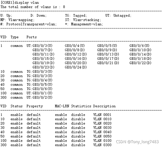
(5)查看配置结果
2.配置CORE2
(1)创建其与接入交换机、备份设备以及园区出口路由器互通的VLAN
[CORE2]vlan batch 10 20 30 40 50 200 300
(2)配置用户侧的接口VLAN和VLANIF,VLANIF接口用于部门之间互访
[CORE2-GigabitEthernet0/0/3]port link-type trunk
[CORE2-GigabitEthernet0/0/3]port trunk allow-pass vlan 10 20
[CORE2]int Vlanif 10
[CORE2-Vlanif10]ip add 10.1.10.2 24
[CORE2-Vlanif10]int Vlanif 20
[CORE2-Vlanif20]ip add 10.1.20.2 24
[CORE2-GigabitEthernet0/0/4]port link-type trunk
[CORE2-GigabitEthernet0/0/4]port trunk allow-pass vlan 30
[CORE2]int Vlanif 30
[CORE2-Vlanif30]ip add 10.1.30.2 24
[CORE2-GigabitEthernet0/0/5]port link-type trunk
[CORE2-GigabitEthernet0/0/5]port trunk allow-pass vlan 40
[CORE2-Vlanif30]int Vlanif 40
[CORE2-Vlanif40]ip add 10.1.40.2 24
[CORE2-GigabitEthernet0/0/6]port link-type trunk
[CORE2-GigabitEthernet0/0/6]port trunk allow-pass vlan 50
[CORE2-Vlanif40]int Vlanif 50
[CORE2-Vlanif50]ip add 10.1.50.2 24
(3)配置连接出口路由器的接口VLAN和VLANIF
[CORE2-GigabitEthernet0/0/1]port link-type access
[CORE2-GigabitEthernet0/0/1]port default vlan 200
[CORE2]int Vlanif 200
[CORE2-Vlanif200]ip add 10.1.2.2 24
(4)配置两个核心交换机直连的接口VLAN和VLANIF
[CORE2-GigabitEthernet0/0/2]port link-type access
[CORE2-GigabitEthernet0/0/2]port default vlan 300
[CORE2]int Vlanif 300
[CORE2-Vlanif300]ip add 10.1.3.2 24
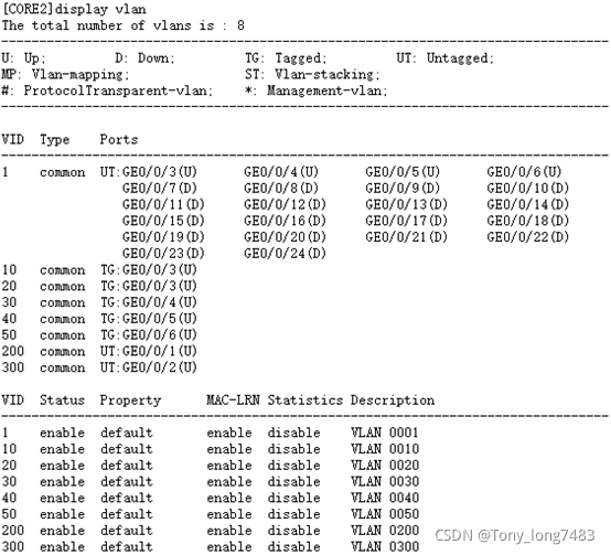
(5)查看配置结果
(三)配置出口路由器和Internet的接口地址
[AR1-GigabitEthernet0/0/1]ip add 10.1.1.3 24
[AR1-GigabitEthernet0/0/2]ip add 10.1.2.3 24
[AR1-GigabitEthernet0/0/1]ip add 20.1.1.3 30
[Internet-GigabitEthernet0/0/0]ip add 20.1.1.1 30
(四)配置静态路由实现网络互通
- 分别在CORE1和CORE2上面分别配置一条缺省静态路由指向出口路由器及其备份路由
[CORE1]ip route-static 0.0.0.0 0.0.0.0 10.1.1.3
[CORE1]ip route-static 0.0.0.0 0.0.0.0 10.1.3.2 preference 70
[CORE2]ip route-static 0.0.0.0 0.0.0.0 10.1.2.3
[CORE2]ip route-static 0.0.0.0 0.0.0.0 10.1.3.1 preference 70 - 在出口路由器配置一条缺省静态路由指向Internet
[AR1]ip route-static 0.0.0.0 0.0.0.0 20.1.1.1 - 在出口路由器配置到内网的主备路由,主路由下一跳指向CORE1,备路由下一跳指向CORE2
[AR1]ip route-static 10.1.10.0 255.255.255.0 10.1.1.1
[AR1]ip route-static 10.1.10.0 255.255.255.0 10.1.2.2 preference 70
[AR1]ip route-static 10.1.20.0 255.255.255.0 10.1.1.1
[AR1]ip route-static 10.1.20.0 255.255.255.0 10.1.2.2 preference 70
[AR1]ip route-static 10.1.30.0 255.255.255.0 10.1.1.1
[AR1]ip route-static 10.1.30.0 255.255.255.0 10.1.2.2 preference 70
[AR1]ip route-static 10.1.40.0 255.255.255.0 10.1.1.1
[AR1]ip route-static 10.1.40.0 255.255.255.0 10.1.2.2 preference 70
[AR1]ip route-static 10.1.50.0 255.255.255.0 10.1.1.1
[AR1]ip route-static 10.1.50.0 255.255.255.0 10.1.2.2 preference 70
(五)配置VRRP主备备份实现虚拟网关冗余:正常情况下用户流量都上送到CORE1进行处理,只有当CORE1出故障之后,VRRP备份组切换CORE2为主设备,用户流量上送到CORE2
1.配置CORE1
[CORE1-Vlanif10]vrrp vrid 1 virtual-ip 10.1.10.254
[CORE1-Vlanif10]vrrp vrid 1 priority 120
[CORE1-Vlanif10]vrrp vrid 1 preempt-mode timer delay 20
[CORE1-Vlanif20]vrrp vrid 2 virtual-ip 10.1.20.254
[CORE1-Vlanif20]vrrp vrid 2 priority 120
[CORE1-Vlanif20]vrrp vrid 2 preempt-mode timer delay 20
[CORE1-Vlanif30]vrrp vrid 3 virtual-ip 10.1.30.254
[CORE1-Vlanif30]vrrp vrid 3 priority 120
[CORE1-Vlanif30]vrrp vrid 3 preempt-mode timer delay 20
[CORE1-Vlanif40]vrrp vrid 4 virtual-ip 10.1.40.254
[CORE1-Vlanif40]vrrp vrid 4 priority 120
[CORE1-Vlanif40]vrrp vrid 4 preempt-mode timer delay 20
[CORE1-Vlanif50]vrrp vrid 5 virtual-ip 10.1.50.254
[CORE1-Vlanif50]vrrp vrid 5 priority 120
[CORE1-Vlanif50]vrrp vrid 5 preempt-mode timer delay 20
2.配置CORE2
[CORE2-Vlanif10]vrrp vrid 1 virtual-ip 10.1.10.254
[CORE2-Vlanif20]vrrp vrid 2 virtual-ip 10.1.20.254
[CORE2-Vlanif30]vrrp vrid 3 virtual-ip 10.1.30.254
[CORE2-Vlanif40]vrrp vrid 4 virtual-ip 10.1.40.254
[CORE2-Vlanif50]vrrp vrid 5 virtual-ip 10.1.50.254
(六)为了避免影响CORE1和CORE2之间VRRP主备备份的状态,在此需要关闭接入交换机连接上行链路接口的stp功能
[ACC1-Ethernet0/0/1]stp disable
[ACC1-Ethernet0/0/2]stp disable
[ACC2-Ethernet0/0/1]stp disable
[ACC2-Ethernet0/0/2]stp disable
[ACC3-Ethernet0/0/1]stp disable
[ACC3-Ethernet0/0/2]stp disable
[ACC4-Ethernet0/0/1]stp disable
[ACC4-Ethernet0/0/2]stp disable
(七)配置出口路由器实现上网 - 配置允许上网的ACL
[AR1]acl 2000
[AR1-acl-basic-2000]rule permit source 10.1.10.0 0.0.0.255
[AR1-acl-basic-2000]rule permit source 10.1.20.0 0.0.0.255
[AR1-acl-basic-2000]rule permit source 10.1.30.0 0.0.0.255
[AR1-acl-basic-2000]rule permit source 10.1.40.0 0.0.0.255
[AR1-acl-basic-2000]rule permit source 10.1.50.0 0.0.0.255
[AR1-acl-basic-2000]rule permit source 10.1.1.0 0.0.0.255
[AR1-acl-basic-2000]rule permit source 10.1.2.0 0.0.0.255
[AR1-acl-basic-2000]rule permit source 10.1.3.0 0.0.0.255 - 在连接Internet的接口配置NAT转换实现内网上网
[AR1-GigabitEthernet0/0/0]nat outbound 2000 - 配置DNS地址解析功能
[AR1]dns resolve
[AR1]dns server 8.8.8.8
[AR1]dns proxy enable
(八)配置DHCP - 配置CORE为DHCP服务器:VRRP组网环境下,为防止主备切换而产生IP地址冲突的问题,因此在配置DHCP服务器时,主设备分配地址段的前一半地址,备设备分配地址段的后一半地址
(1)配置CORE1
[CORE1]dhcp enable
[CORE1]ip pool 10
[CORE1-ip-pool-10]gateway-list 10.1.10.254
[CORE1-ip-pool-10]network 10.1.10.0 mask 24
[CORE1-ip-pool-10]excluded-ip-address 10.1.10.128 10.1.10.254
[CORE1-ip-pool-10]lease day 0 hour 20 minute 0
[CORE1-ip-pool-10]dns-list 8.8.8.8
[CORE1-ip-pool-10]ip pool 20
[CORE1-ip-pool-20]gateway-list 10.1.20.254
[CORE1-ip-pool-20]network 10.1.20.0 mask 24
[CORE1-ip-pool-20]excluded-ip-address 10.1.20.128 10.1.20.253
[CORE1-ip-pool-20]lease day 0 hour 20 minute 0
[CORE1-ip-pool-20]dns-list 8.8.8.8
[CORE1-ip-pool-20]ip pool 30
[CORE1-ip-pool-30]gateway-list 10.1.30.254
[CORE1-ip-pool-30]network 10.1.30.0 mask 24
[CORE1-ip-pool-30]excluded-ip-address 10.1.30.128 10.1.30.253
[CORE1-ip-pool-30]dns-list 8.8.8.8
[CORE1-ip-pool-30]lease day 0 hour 20 minute 0
[CORE1-ip-pool-30]ip pool 40
[CORE1-ip-pool-40]gateway-list 10.1.40.254
[CORE1-ip-pool-40]network 10.1.40.0 mask 24
[CORE1-ip-pool-40]excluded-ip-address 10.1.40.128 10.1.40.253
[CORE1-ip-pool-40]lease day 0 hour 20 minute 0
[CORE1-ip-pool-40]dns-list 8.8.8.8
[CORE1-ip-pool-40]ip pool 50
[CORE1-ip-pool-50]gateway-list 10.1.50.254
[CORE1-ip-pool-50]network 10.1.50.0 mask 24
[CORE1-ip-pool-50]excluded-ip-address 10.1.50.128 10.1.50.253
[CORE1-ip-pool-50]dns-list 8.8.8.8
[CORE1-ip-pool-50]lease day 0 hour 20 minute 0
(2)配置CORE2
[CORE2]dhcp enable
[CORE2]ip pool 10
[CORE2-ip-pool-10]gateway-list 10.1.10.254
[CORE2-ip-pool-10]network 10.1.10.0 mask 24
[CORE2-ip-pool-10]excluded-ip-address 10.1.10.1 10.1.10.127
[CORE2-ip-pool-10]lease day 0 hour 20 minute 0
[CORE2-ip-pool-10]dns-list 8.8.8.8
[CORE2-ip-pool-10]ip pool 20
[CORE2-ip-pool-20]network 10.1.20.0 mask 24
[CORE2-ip-pool-20]gateway-list 10.1.20.254
[CORE2-ip-pool-20]excluded-ip-address 10.1.20.1 10.1.20.127
[CORE2-ip-pool-20]dns-list 8.8.8.8
[CORE2-ip-pool-20]lease day 0 hour 20 minute 0
[CORE2-ip-pool-20]ip pool 30
[CORE2-ip-pool-30]gateway-list 10.1.30.254
[CORE2-ip-pool-30]network 10.1.30.0 mask 24
[CORE2-ip-pool-30]excluded-ip-address 10.1.30.1 10.1.30.127
[CORE2-ip-pool-30]dns-list 8.8.8.8
[CORE2-ip-pool-30]lease day 0 hour 20 minute 0
[CORE2-ip-pool-30]ip pool 40
[CORE2-ip-pool-40]gateway-list 10.1.40.254
[CORE2-ip-pool-40]network 10.1.40.0 mask 24
[CORE2-ip-pool-40]excluded-ip-address 10.1.40.1 10.1.40.127
[CORE2-ip-pool-40]lease day 0 hour 20 minute 0
[CORE2-ip-pool-40]dns-list 8.8.8.8
[CORE2-ip-pool-30]ip pool 50
[CORE2-ip-pool-50]gateway-list 10.1.50.254
[CORE2-ip-pool-50]network 10.1.50.0 mask 24
[CORE2-ip-pool-50]excluded-ip-address 10.1.50.1 10.1.50.127
[CORE2-ip-pool-50]dns-list 8.8.8.8
[CORE2-ip-pool-50]lease day 0 hour 20 minute 0
(3)配置用户从全局地址池获取IP地址
[CORE1-Vlanif10]dhcp select global
[CORE1-Vlanif20]dhcp select global
[CORE1-Vlanif30]dhcp select global
[CORE1-Vlanif40]dhcp select global
[CORE1-Vlanif50]dhcp select global
[CORE2-Vlanif10]dhcp select global
[CORE2-Vlanif30]dhcp select global
[CORE2-Vlanif40]dhcp select global
[CORE2-Vlanif50]dhcp select global
(4)配置完动态分配地址之后,刚开电脑获取地址的时间比较长,这是因为对于开启了生成树协议的交换机,每当有电脑接入之后导致生成树重新计算收敛,所以需要的时间比较长;通过关闭接口的生成树协议或者把连接终端的交换机接口配置为边缘端口即可解决
[ACC1-Ethernet0/0/3]stp disable
[ACC1-Ethernet0/0/4]stp disable
[ACC2-Ethernet0/0/3]stp edged-port enable
[ACC2-Ethernet0/0/4]stp edged-port enable
[ACC3-Ethernet0/0/3]stp disable
[ACC3-Ethernet0/0/4]stp disable
[ACC4-Ethernet0/0/3]stp edged-port enable
[ACC4-Ethernet0/0/4]stp edged-port enable
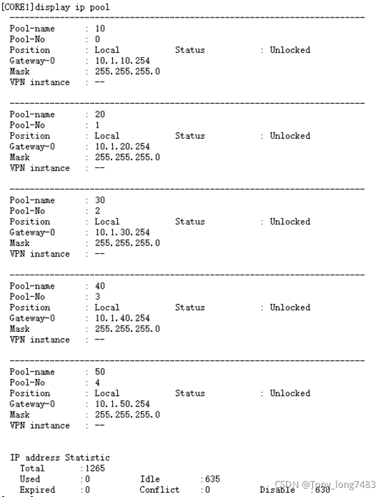
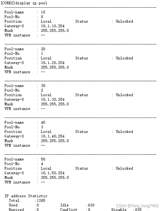
(5)查看全局地址池的配置和使用情况
- 配置DHCP Snooping和IPSG:配置DHCP Snooping和IPSG
(1)在接入交换机上开启DHCP Snooping功能
[ACC1]dhcp enable
[ACC1]dhcp snooping enable
[ACC2]dhcp enable
[ACC2]dhcp snooping enable
[ACC3]dhcp enable
[ACC3]dhcp snooping enable
[ACC4]dhcp enable
[ACC4]dhcp snooping enable
(2)在连接终端的接口上使能DHCP Snooping功能
[ACC1-Ethernet0/0/3]dhcp snooping enable
[ACC1-Ethernet0/0/4]dhcp snooping enable
[ACC2-Ethernet0/0/3]dhcp snooping enable
[ACC2-Ethernet0/0/4]dhcp snooping enable
[ACC3-Ethernet0/0/3]dhcp snooping enable
[ACC3-Ethernet0/0/4]dhcp snooping enable
[ACC4-Ethernet0/0/3]dhcp snooping enable
[ACC4-Ethernet0/0/4]dhcp snooping enable
(3)在连接DHCP服务器的接口上使能DHCP Snooping功能,并将此接口配置为信任接口
[ACC1-Ethernet0/0/1]dhcp snooping enable
[ACC1-Ethernet0/0/1]dhcp snooping trusted
[ACC1-Ethernet0/0/2]dhcp snooping enable
[ACC1-Ethernet0/0/2]dhcp snooping trusted
[ACC2-Ethernet0/0/1]dhcp snooping enable
[ACC2-Ethernet0/0/1]dhcp snooping trusted
[ACC2-Ethernet0/0/2]dhcp snooping enable
[ACC2-Ethernet0/0/2]dhcp snooping trusted
[ACC3-Ethernet0/0/1]dhcp snooping enable
[ACC3-Ethernet0/0/1]dhcp snooping trusted
[ACC3-Ethernet0/0/2]dhcp snooping enable
[ACC3-Ethernet0/0/2]dhcp snooping trusted
[ACC4-Ethernet0/0/1]dhcp snooping enable
[ACC4-Ethernet0/0/1]dhcp snooping trusted
[ACC4-Ethernet0/0/2]dhcp snooping enable
[ACC4-Ethernet0/0/2]dhcp snooping trusted
(4)为了防止部门内用户私自更改IP地址后攻击网络,在接入交换机开启DHCP Snooping功能后,还需要开启IP报文检查功能,这样从VLAN收到报文后会将报文与动态绑定表的表项进行匹配,放行匹配的报文,丢弃不匹配的报文。如果不想对整个VLAN收到的报文进行检查,可以只在连接某个终端的接口上开启IP报文检查功能
[ACC1]vlan 10
[ACC1-vlan10]ip source check user-bind enable
[ACC1-vlan10]vlan 20
[ACC1-vlan20]ip source check user-bind enable
[ACC2]vlan 30
[ACC2-vlan30]ip source check user-bind enable
[ACC3]vlan 40
[ACC3-vlan40]ip source check user-bind enable
[ACC4]vlan 50
[ACC4-vlan50]ip source check user-bind enable
(九)用OSPF路由协议替换静态路由 - 删除核心交换机的静态路由配置
[CORE1]undo ip route-static all
[CORE2]undo ip route-static all - 删除出口路由器到内网的静态路由,保留到internet的缺省路由
[AR1]undo ip route-static 10.1.10.0 24
[AR1]undo ip route-static 10.1.20.0 24
[AR1]undo ip route-static 10.1.30.0 24
[AR1]undo ip route-static 10.1.40.0 24
[AR1]undo ip route-static 10.1.50.0 24 - CORE1的OSPF配置
[CORE1]ospf 1
[CORE1-ospf-1]area 0
[CORE1-ospf-1-area-0.0.0.0]network 10.1.10.0 0.0.0.255
[CORE1-ospf-1-area-0.0.0.0]network 10.1.20.0 0.0.0.255
[CORE1-ospf-1-area-0.0.0.0]network 10.1.30.0 0.0.0.255
[CORE1-ospf-1-area-0.0.0.0]network 10.1.40.0 0.0.0.255
[CORE1-ospf-1-area-0.0.0.0]network 10.1.50.0 0.0.0.255
[CORE1-ospf-1-area-0.0.0.0]network 10.1.1.0 0.0.0.255
[CORE1-ospf-1-area-0.0.0.0]network 10.1.3.0 0.0.0.255 - CORE2的OSPF配置
[CORE2]ospf 1
[CORE2-ospf-1]area 0
[CORE2-ospf-1-area-0.0.0.0]network 10.1.10.0 0.0.0.255
[CORE2-ospf-1-area-0.0.0.0]network 10.1.20.0 0.0.0.255
[CORE2-ospf-1-area-0.0.0.0]network 10.1.30.0 0.0.0.255
[CORE2-ospf-1-area-0.0.0.0]network 10.1.40.0 0.0.0.255
[CORE2-ospf-1-area-0.0.0.0]network 10.1.50.0 0.0.0.255
[CORE2-ospf-1-area-0.0.0.0]network 10.1.2.0 0.0.0.255
[CORE2-ospf-1-area-0.0.0.0]network 10.1.3.0 0.0.0.255 - 出口路由器的OSPF配置,为了连接内网和Internet需要配置指向Internet的静态缺省路由,在OSPF进程需要引入缺省路由,同时需要配置一条缺省静态路由指向Internet
[AR1]ospf 1
[AR1-ospf-1]default-route-advertise always
[AR1-ospf-1-area-0.0.0.0]network 10.1.1.0 0.0.0.255
[AR1-ospf-1-area-0.0.0.0]network 10.1.2.0 0.0.0.255
(十)配置可靠性和负载分担 - 配置VRRP联动接口检测链路:主备设备的上行接口出现故障的时通过配置VRRP与接口状态联动功能可以实现此快速切换
[CORE1-Vlanif10]vrrp vrid 1 track interface g0/0/1 reduced 100
[CORE1-Vlanif20]vrrp vrid 2 track interface g0/0/1 reduced 100
[CORE1-Vlanif30]vrrp vrid 3 track interface g0/0/1 reduced 100
[CORE1-Vlanif40]vrrp vrid 4 track interface g0/0/1 reduced 100
[CORE1-Vlanif50]vrrp vrid 5 track interface g0/0/1 reduced 100
[CORE2-Vlanif10]vrrp vrid 1 track interface g0/0/1 reduced 100
[CORE2-Vlanif20]vrrp vrid 2 track interface g0/0/1 reduced 100
[CORE2-Vlanif30]vrrp vrid 2 track interface g0/0/1 reduced 100
[CORE2-Vlanif40]vrrp vrid 4 track interface g0/0/1 reduced 100
[CORE2-Vlanif50]vrrp vrid 5 track interface g0/0/1 reduced 100 - 配置负载分担:把VRRP主备备份配置为负载分担,一些VLAN以CORE1为主设备,另一些VLAN以CORE2为主设备,不同VLAN的流量被分配到了左右两条链路上,有效的利用现网资源
(1)删除CORE1上面VRRP备份组2、4的优先级和抢占延时配置
[CORE1-Vlanif20]undo vrrp vrid 2 preempt-mode timer delay
[CORE1-Vlanif20]undo vrrp vrid 2 priority
[CORE1-Vlanif40]undo vrrp vrid 4 preempt-mode timer delay
[CORE1-Vlanif40]undo vrrp vrid 4 priority
(2)配置CORE2为VLAN20、40的主设备,抢占延时为20S
[CORE2-Vlanif20]vrrp vrid 2 priority 120
[CORE2-Vlanif20]vrrp vrid 2 preempt-mode timer delay 20
[CORE2-Vlanif40]vrrp vrid 4 priority 120
[CORE2-Vlanif40]vrrp vrid 4 preempt-mode timer delay 20
(十一)配置链路聚合 - 恢复接口默认配置
[CORE1-GigabitEthernet0/0/2]undo port default vlan
[CORE1-GigabitEthernet0/0/2]undo port link-type
[CORE2-GigabitEthernet0/0/2]undo port default vlan
[CORE2-GigabitEthernet0/0/2]undo port link-type - 配置链路聚合:有手工负载分担方式(默认)和LACP模式
[CORE1]int Eth-Trunk 1
[CORE1-Eth-Trunk1]mode lacp
[CORE1-Eth-Trunk1]trunkport g0/0/2
[CORE1-Eth-Trunk1]trunkport g0/0/7
[CORE1]lacp priority 100 //配置系统优先级为100,使其成为LACP主动端
[CORE1-Eth-Trunk1]max active-linknumber 2
[CORE1-GigabitEthernet0/0/2]lacp priority 100 //配置接口优先级确定活动链路
[CORE1-GigabitEthernet0/0/7]lacp priority 100
[CORE2]int Eth-Trunk 1
[CORE2-Eth-Trunk1]mode lacp
[CORE2-Eth-Trunk1]trunkport g0/0/2
[CORE2-Eth-Trunk1]trunkport g0/0/7
[CORE2-Eth-Trunk1]max active-linknumber 2
[CORE2]lacp priority 100
[CORE2-GigabitEthernet0/0/2]lacp priority 100
[CORE2-GigabitEthernet0/0/7]lacp priority 100
(十二)配置限速 - 基于IP地址对A限速:只能在AR路由器上配置每IP限速
[AR1-GigabitEthernet0/0/1]qos car inbound source-ip-address range 10.1.10.1 to 10.1.10.254 per-address cir 1024
[AR1-GigabitEthernet0/0/1]qos car outbound destination-ip-address range 10.1.10.1 to 10.1.10.254 per-address cir 1024
[AR1-GigabitEthernet0/0/2]qos car inbound source-ip-address range 10.1.10.1 to 10.1.10.254 per-address cir 1024
[AR1-GigabitEthernet0/0/2]qos car outbound destination-ip-address range 10.1.10.1 to 10.1.10.254 per-address cir 1024 - 基于网段总流量对B限速
[AR1]acl 2000
[AR1-acl-basic-2000]rule permit source 10.1.20.0 0.0.0.255
[AR1-GigabitEthernet0/0/1]qos car inbound acl 2000 cir 2048 //访问网络速度为2M
[AR1-GigabitEthernet0/0/1]qos car outbound acl 2000 cir 4096 //下载速度为4M
[AR1-GigabitEthernet0/0/2]qos car inbound acl 2000 cir 2048
[AR1-GigabitEthernet0/0/2]qos car outbound acl 2000 cir 4096
(十三)配置映射内网服务器和公网多出口
-
配置内部服务器,使公网用户通过公网地址访问内网服务器
[AR1-GigabitEthernet0/0/0]nat server protocol tcp global current-interface www inside 10.1.50.10 www
[AR1-GigabitEthernet0/0/0]nat server protocol tcp global current-interface ftp inside 10.1.50.20 ftp -
由于FTP是一个多通道协议,需要在出口路由器使能ALG功能
[AR1]nat alg ftp enable -
配置内网用户使用公网地址访问内网服务器
[AR1]acl 3000
[AR1-acl-adv-3000]rule permit ip source 10.1.10.0 0.0.0.255 destination 20.1.50.1 0.0.0.0
[AR1-acl-adv-3000]rule permit ip source 10.1.20.0 0.0.0.255 destination 20.1.50.1 0.0.0.0
[AR1-acl-adv-3000]rule permit ip source 10.1.30.0 0.0.0.255 destination 20.1.50.1 0.0.0.0
[AR1-acl-adv-3000]rule permit ip source 10.1.40.0 0.0.0.255 destination 20.1.50.1 0.0.0.0 -
在内网接口做NAT转换
[AR1-GigabitEthernet0/0/1]nat outbound 3000
[AR1-GigabitEthernet0/0/2]nat outbound 3000 -
分别在内网接口下面做内部服务器映射
[AR1-GigabitEthernet0/0/1]nat server protocol tcp global 20.1.50.1 www inside 10.1.50.10 www
[AR1-GigabitEthernet0/0/1]nat server protocol tcp global 20.1.50.1 ftp inside 10.1.50.10 ftp
(十五)验证 -
从两个部门内各选一台PC进行ping测试,如果测试正常则说明三层互通正常
-
部门内部选两台PC进行ping测试,如果测试正常则说明部门内二层互通正常
-
每个部门各选一台PC进行ping公网地址测试,如果测试正常则说明内网用户访问Internet正常


 4094
4094

 被折叠的 条评论
为什么被折叠?
被折叠的 条评论
为什么被折叠?
 到【灌水乐园】发言


