


一、实验要求:
1、内分配网IP地址使用172.16.0.0/16
2、sw1和sw2之间互为备份
3、使用VRRP/STP/VLAN/Eth-trunk
4、所有PC均通过DHCP方式获取IP地址
5、ISP只能用来配置IP地址
6、所有电脑都可以正常访问ISP路由器环回
以下是配置的拓扑图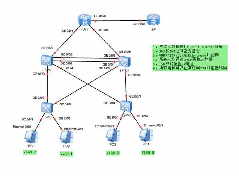
二、实验准备:
1、实验设备:
四个S5700交换机,四台PC主机,两台路由器
2、实验配置主要步骤概述:
(1)、创建VLAN
(2)、配置聚合链路Eth-trunk
(3)、将所有交换机的接口划分到VLAN中
(4)、配置MSTP多生成树
(5)、在三层交换机上配置SVI虚拟网关
(6)、配置VRRP虚拟路由器冗余协议
(7)、利用DHCP配置IP地址
(8)、配置NAT网络地址转换
3、实验步骤详细介绍:
(1)、创建VLAN
对四个交换机分别创建VLAN 2和VLAN 3,对交换机s1和s2创建VLAN 10 和VLAN 20。
#对于交换机LSW1:
<Huawei>sys
[Huawei]sys s1
[s1]vlan batch 2 3 10 20
#对于交换机LSW2:
<Huawei>sys
[Huawei]sys s2
[s2]vlan batch 2 3 10 20
#对于交换机LSW3:
<Huawei>sys
[Huawei]sys s3
[s3]vlan batch 2 3
#对于交换机LSW4:
<Huawei>sys
[Huawei]sys s4
[s4]vlan batch 2 3
(2)、配置聚合链路Eth-trunk
将交换机s1和交换机s2之间的两条链路配置为聚合链路。
#对于交换机s1:
[s1]interface Eth-Trunk 0
[s1-Eth-Trunk0]trunkport g 0/0/1 g 0/0/2
#对于交换机s2:
[s2]interface Eth-Trunk 0
[s2-Eth-Trunk0]trunkport g 0/0/1 g 0/0/2
(3)、将所有交换机的接口划分到VLAN中
为四个交换机配置Trunk链路和Access链路。
#对于交换机s1:
[s1]port-group group-member g0/0/3 to g0/0/4
[s1-port-group]port link-type trunk
[s1-port-group]port trunk allow-pass vlan 2 3
[s1]interface Eth-Trunk 0
[s1-Eth-Trunk0]port link-type trunk
[s1-Eth-Trunk0]port trunk allow-pass vlan 2 3
[s1]interface g 0/0/5
[s1-GigabitEthernet0/0/5]port link-type  access
[s1-GigabitEthernet0/0/5]port default  vlan 10
#对于交换机s2:
[s2]port-group group-member g0/0/3 to g0/0/4
[s2-port-group]port link-type trunk
[s2-port-group]port trunk allow-pass vlan 2 3
[s2]interface Eth-Trunk 0
[s2-Eth-Trunk0]port link-type trunk
[s2-Eth-Trunk0]port trunk allow-pass vlan 2 3
[s2]interface g 0/0/5
[s2-GigabitEthernet0/0/5]port link-type  access
[s2-GigabitEthernet0/0/5]port default  vlan 10
#对于交换机s3:
[s3]interface g 0/0/1
[s3-GigabitEthernet0/0/1]port link-type access
[s3-GigabitEthernet0/0/1]port default vlan 2
[s3-GigabitEthernet0/0/1]interface g 0/0/2
[s3-GigabitEthernet0/0/2]port link-type access
[s3-GigabitEthernet0/0/2]port default vlan 3
[s3]port-group group-member  g0/0/3 to g0/0/4
[s3-port-group]port link-type trunk
[s3-port-group]port trunk allow-pass vlan 2 3
#对于交换机s4:
[s4]interface g 0/0/1
[s4-GigabitEthernet0/0/1]port link-type access
[s4-GigabitEthernet0/0/1]port default vlan 2
[s4-GigabitEthernet0/0/1]interface g 0/0/2
[s4-GigabitEthernet0/0/2]port link-type access
[s4-GigabitEthernet0/0/2]port default vlan 3
[s4]port-group group-member  g0/0/3 to g0/0/4
[s4-port-group]port link-type trunk
[s4-port-group]port trunk allow-pass vlan 2 3
(4)、配置MSTP多生成树
启用多生成树进行配置,对s1和s2进行根网桥的配置以及s3和s4边缘端口的保护。
#对于交换机s1:
[s1]stp enable
[s1]stp mode mstp
[s1]stp region-configuration
[s1-mst-region]region-name aa
[s1-mst-region]instance 1 vlan 2
[s1-mst-region]instance 2 vlan 3
[s1-mst-region]active region-configuration
[s1]stp instance 1 root primary
[s1]stp instance 2 root secondary
#对于交换机s2:
[s2]stp enable
[s2]stp mode mstp
[s2]stp region-configuration
[s2-mst-region]region-name aa
[s2-mst-region]instance 1 vlan 2
[s2-mst-region]instance  2 vlan 3
[s2-mst-region]active region-configuration
[s2]stp instance 1 root secondary
[s2]stp instance 2 root primary
#对于交换机s3:
[s3]stp enable
[s3]stp mode mstp
[s3]stp region-configuration
[s3-mst-region]region-name aa
[s3-mst-region]instance 1 vlan 2
[s3-mst-region]instance 2 vlan 3
[s3-mst-region]active region-configuration
[s3]port-group group-member GigabitEthernet 0/0/1 to 0/0/2
[s3-port-group]stp edged-port enable
[s3-GigabitEthernet0/0/1]stp edged-port enable
[s3-GigabitEthernet0/0/2]stp edged-port enable
[s3]stp bpdu-protection
#对于交换机s4:
[s4]stp enable
[s4]stp mode mstp
[s4]stp region-configuration
[s4-mst-region]region-name  aa
[s4-mst-region]instance 1 vlan 2
[s4-mst-region]instance 2 vlan 3
[s4-mst-region]active region-configuration
[s4]port-group group-member GigabitEthernet 0/0/1 to 0/0/2
[s4-port-group]stp edged-port enable
[s4-GigabitEthernet0/0/1]stp edged-port enable
[s4-GigabitEthernet0/0/2]stp edged-port enable
[s4]stp bpdu-protection
(5)、在三层交换机上配置SVI虚拟网关
在s1和s2上创建虚拟网关。
#对于交换机s1:
[s1]interface Vlanif 2
[s1-Vlanif2]ip address 172.16.2.1 24
[s1-Vlanif2]int v 3
[s1-Vlanif3]ip add 172.16.3.1 24
[s1-Vlanif3]int v 10
[s1-Vlanif10]ip add 172.16.0.0 30
#对于交换机s2:
[s2]interface Vlanif 2
[s2-Vlanif2]ip address 172.16.2.2 24
[s2-Vlanif2]int v 3
[s2-Vlanif3]ip add 172.16.3.2 24
[s2-Vlanif3]int v 10
[s2-Vlanif10]ip add 172.16.0.4 30
(6)、配置VRRP虚拟路由器冗余协议
对交换机s1和s2进行VRRP配置。
#对于交换机s1:
[s1]interface Vlanif 2
[s1-Vlanif2]vrrp vrid 2 virtual-ip 172.16.2.254
[s1-Vlanif2]vrrp vrid 2 priority 110
[s1]interface Vlanif 3
[s1-Vlanif3]vrrp vrid 3 virtual-ip 172.16.3.254
#对于交换机s2:
[s2]interface Vlanif 2
[s2-Vlanif2]vrrp vrid 2 virtual-ip 172.16.2.254
[s2]interface Vlanif 3
[s2-Vlanif3]vrrp vrid 3 virtual-ip 172.16.3.254
[s2-Vlanif3]vrrp vrid 3 priority 110
(7)、利用DHCP配置IP地址
对交换机s1和s2配置DHCP。
#对于交换机s1:
[s1]dhcp enable
[s1]ip pool v2
[s1-ip-pool-v2]network 172.16.2.0 mask 24
[s1-ip-pool-v2]gateway-list 172.16.2.254
[s1]ip pool v3
[s1-ip-pool-v3]network 172.16.3.0 mask 24
[s1-ip-pool-v3]gateway-list 172.16.3.254
[s1]int v 2
[s1-Vlanif2]dhcp select global
[s1]int v 3
[s1-Vlanif3]dhcp select global
 #对于交换机s2:
[s2]dhcp enable
[s2]ip pool v2
[s2-ip-pool-v2]network 172.16.2.0 mask 24
[s2-ip-pool-v2]gateway-list 172.16.2.254
[s2]ip pool v3
[s2-ip-pool-v3]network 172.16.3.0 mask 24
[s2-ip-pool-v3]gateway-list 172.16.3.254
[s2]int v 2
[s2-Vlanif2]dhcp select global
[s2]int v 3
[s2-Vlanif3]dhcp select global
(8)、配置NAT网络地址转换
实现VLAN之间的互通,并且配置NAT网络地址转换,将私网地址转换为公网地址。
#VLAN间的互通
#对于交换机s1:
[s1]interface vlanif 10
[s1-Vlanif10]ip add 172.16.0.1 30
#对于交换机s2:
[s2]int v 10
[s2-Vlanif10]ip add 172.16.0.5 30
#路由器和ISP的配置:
[AR1]int g0/0/1
[AR1-GigabitEthernet0/0/1]ip add 172.16.0.2 30
[AR1-GigabitEthernet0/0/1]int g0/0/2
[AR1-GigabitEthernet0/0/2]ip add 172.16.0.6 30
[AR1-GigabitEthernet0/0/2]int g0/0/0
[AR1-GigabitEthernet0/0/0]ip add 12.0.0.1 24
[ISP]int g0/0/0
[ISP-GigabitEthernet0/0/0]ip add 12.0.0.2 24
[ISP-GigabitEthernet0/0/0]int l0
[ISP-LoopBack0]ip add 1.1.1.1 24
[AR1]ip route-static 0.0.0.0 0 12.0.0.2
[AR1]ospf 1 router-id 1.1.1.1
[AR1-ospf-1]a 0
[AR1-ospf-1-area-0.0.0.0]network 172.16.0.2 0.0.0.0
[AR1-ospf-1-area-0.0.0.0]network 172.16.0.6 0.0.0.0
#对于交换机s1:
[s1]ospf 1 router-id 2.2.2.2
[s1-ospf-1]a 0
[s1-ospf-1-area-0.0.0.0]network 172.16.2.1 0.0.0.0
[s1-ospf-1-area-0.0.0.0]network 172.16.3.2 0.0.0.0
[s1-ospf-1-area-0.0.0.0]network 172.16.0.1 0.0.0.0
#对于交换机s2:
[s2]ospf 1 router-id 3.3.3.3
[s2-ospf-1]a 0
[s2-ospf-1-area-0.0.0.0]network 172.16.2.2 0.0.0.0
[s2-ospf-1-area-0.0.0.0]network 172.16.3.1 0.0.0.0
[s2-ospf-1-area-0.0.0.0]network 172.16.0.5 0.0.0.0
# 下发缺省
[AR1-ospf-1]default-route-advertise
#NAT配置:
通过ACL,使内网能够访问公网
[AR1]acl 2000
[AR1-acl-basic-2000]rule permit source 172.16.0.0 0.0.255.255
[AR1]int g0/0/0
[AR1-GigabitEthernet0/0/0]nat outbound 2000
三、实验总结
通过这次实验,大体了解了交换机之间MSTP与VRRP技术相结合的特点,也明白了关于VLAN方面的一些简单配置,以后在配置这些较为复杂的交换网络结构时,首先一点就是要明白从哪里开始下手,只有捋清了这所有的配置步骤,之后的工作才会水到渠成,难度也会变得更加的得心应手。


 6548
6548

 被折叠的 条评论
为什么被折叠?
被折叠的 条评论
为什么被折叠?
 到【灌水乐园】发言


